40 electric duct heater wiring diagram
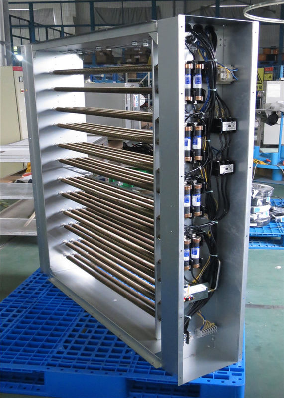
Make sure line and control voltage of system matches that noted on wiring diagram. Wire in accordance with N.E.C. and any existing local codes. Check tightness of all factory and field electrical connections. Make sure fan interlock is wired in if the Heater does not have an air flow switch. Use 90 deg. C (194 deg. F) copper wire. ElEctric coils priceindustries.com | ELEctrIc coILs - Manual 3 iNstAllAtioN AND MoUNtiNG iNstrUctioNs Heater control Panel The heater control panel houses all elements that are required to power up your
FINNED TUBE ELECTRIC - DUCT HEATER Standard Control Options (129.81 KB) FINNED TUBE ELECTRIC - DUCT HEATER How To Size Duct Heaters (231.04 KB) Front Fan Guards Sales Flyer (65.25 KB) Front Fan Guards Submittal Sheet (137.03 KB) FRP/FRS SERIES - INFRARED HEATER Sales Flyer (880.78 KB)
Electric duct heater wiring diagram
Each electric duct heater's unique design allows air to flow freely for the lowest possible pressure drop. Our heaters are factory-assembled and wired for the electrical specialties and controls of each project, and are available with round duct connection collars. The heaters are shipped loose, can be duct-installed onsite and are designed of open coil and finned tubular duct heaters within minutes. With this software, your local INDEECO representative becomes the source for certified prints, wiring diagrams — complete submittal information. Our heaters and controls range from the simplest standard duct heater to the most sophisticated, custom designed comprehensive system. Duct Heaters. 227 Series IOM. Electric Duct Heater Owner's Manual. Instructions for Electric Duct Heaters with Type 3R Terminal Boxes. User Manual - Process Air Heaters. Instructions for Field Replacement of Resistance Open Coil Elements in Brasch Duct Heaters. Unit Heaters. 233 Series IOM. 233 Series Core Replacement. 233 Series Pole ...
Electric duct heater wiring diagram. WIRING DIAGRAMS ENGINEERING SECTION NEC & UL REQUIREMENTS HEATER CONFIGURATIONS SUGGESTED SPECIFICATIONS COMPONENTS OPTIONS & ACCESSORIES. GENERAL OVERVIEW A ELECTRIC DUCT HEATERS TABLE OF CONTENTS Page No. General Overview 1 Nailor Models 2 Control Panel Features 3 Components Options & Accessories 4 Construction & Dimensional Data 10 www.supercoolsliderule.com -- This video tutorial will illustrate with a wiring schematic and photos how an electric heater operates. Some troubleshooting wi... duct heater consists of attaching round duct to the inlet and outlet collars and bolting in place. Seal connection and duct joint. Model RCMP (Remote Control Panel) Install the control panel in a suitable location for the specified panel type. The wiring diagrams inside the heater door and the remote control panel door show point-to-point interconnecting Trench Style Convection Heaters: 9900 Series; Architectural Sill Line Heaters: 9100 Series ... L Series Duct Heater Thermostat SDHW RS 24 Volt Duct Heat Thermostat; Unit Style Heaters: 2600 Series ... Electric Infrared Heaters: FSS Series 14 & 31 ...
Electric Duct Heaters. Open coil heaters. Installation Instructions (47.66kb) Download document Tubular element heaters. Installation Instructions (47.66kb) Download document Thermo-Air. Instruction Manual (66.13kb) Download document ... 41 Typical Wiring Diagrams More Brasch Products Contents. 2 www.braschmfg.com ... is used in all Brasch duct heaters. This iron-free wire has a higher maximum operating temperature, greater life, lower ... Electric heaters differ from steam or hot water coils in that Wiring Diagrams. A specific wiring diagram for each heater including all controls is glued to the inside of the control panel door. Another wiring diagram is provided loose in the control box. Heater Element Rack Replacement For Series Fan Powered Terminal Units. On series fan Powered Terminal Units, the element rack is removable for replacement. or greater as defined on the wiring diagram. Use aluminum wire only when specifically called for on accompanying wiring diagram. 16. If supply connections are for 250 volts or greater, all wiring must be . insulated for 600 volts. 17. When making line connections to heater element terminals FOR FINNED TUBULAR DUCT HEATERS ONLY, apply a wrench ...
These duct heaters are not intended for installation in series in the air- stream; the heaters are designed for use only as a single unit within a duct ... Follow the wiring diagram on the inside of the terminal box. 15. ... National Electric Code for 75 °C copper wire with not more than 3 conductors in a raceway. The amperages shown are for ... catalog 06 electric duct heaters ul & csa listed electric duct heaters stock- line series • quicksilver series • custom built series warren t e c h n o l o g y , i n c 2050 west 73 street hialeah, fl 33016 • telephone: (305) 556-6933 • fax: (305) 557-6157 Electric Finned Tubular DUCT HEATERS CONTENTS Introduction 04 Special Constructions 17 Wiring Diagrams 19 Warning & Nomenclature & Serial 05 Commercial Type Duct Heaters 20 Number Duct Heater Specification 21 Certifications & Registrations 22 Construction Details 06 HSE Policy & Awards 23 Manufacturing 24 Types 08 Warehouses 25 Showrooms 26 Technical Data 10 Installation 12 Finned Heating ... the heating section of the heater. Slide the heater into the duct. Use the holes in the controls box as a template for locating the mounting holes in the duct. Remove the heater and drill mounting holes. Replace the heater and mount into the duct with sheet metal screws. Connect the high and low voltage wiring as shown on the attached wiring ...
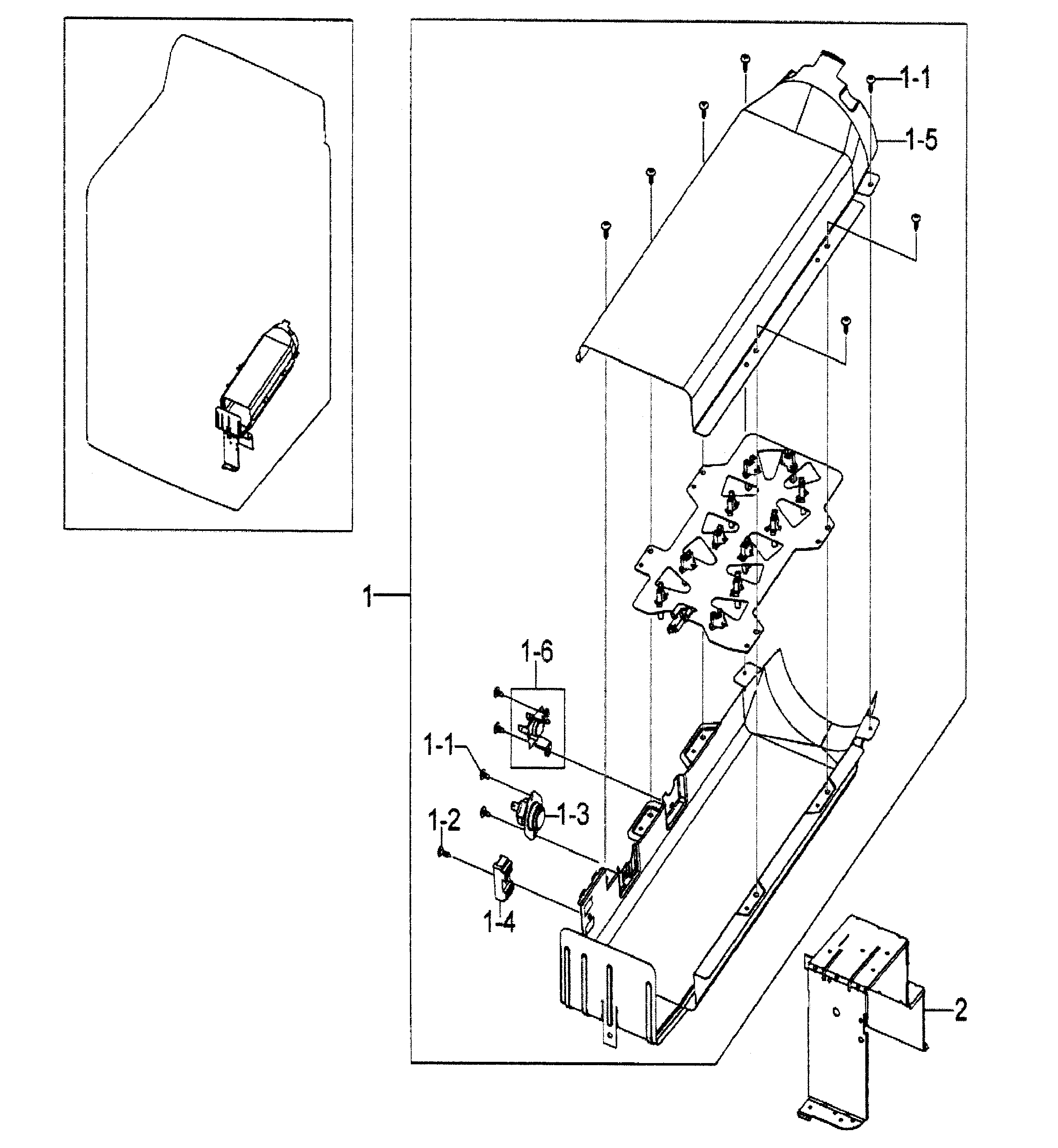
Samsung DV5451AEWXAA Heater Duct Assembly (2 Wire ...
A duct heater must be installed according to the installations instructions, wiring diagram and labeling supplied with the heater. Listed below are some important items when installing an electric duct heater: 1. Never operate a duct heater without airflow. The heater must always be interlocked with the fan. This may be accomplished by either an

Series EP2 Explosion-proof Division 2 Duct Heaters
EK Series Electric Duct Heater OPTIONS & ACCESSORIES Specifi cations may be subject to change without notice. 0 25 50 75 100 125 150 175 200 0 2500 5000 7500 10000 12500 HEATER CAPACITY -kW AIRFLOW - CFM EK Series Heater Capacity SAFE OPERATING RANGE EK SERIES HEATER CAPACITY ELECTRIC DUCT HEATER SPECIFICATIONS Heater Type: Electric Duct ...

help wiring inline duct heater - D.I.Y. Kit - UK420
A wiring diagram is an easy visual depiction of the physical connections as well as physical format of an electrical system or circuit. It demonstrates how the electric cables are adjoined and also can also reveal where components as well as parts could be attached to.Warren Technology CBK Custom Built Electric Duct Heaters for Commercial HVAC ...

Heater Plug Wiring Diagram - MORPHINE-AND-DRUGS
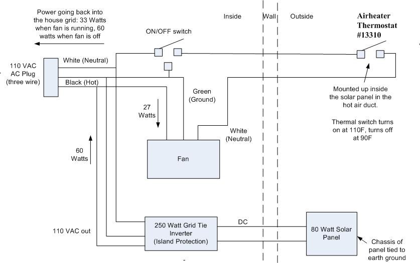
Duct heaters are designed for heating of intake fresh air transported through ... The electric heater wiring diagram is shown at the internal wall of the ...

Gretsch Guitar
Valid Air® High Performance Air Diffusers. Zebra Precision Air Valves. Electric Heating Products. Unitary Electric Heaters. Stock-line Duct Heaters. Quicksilver Duct Heaters. Custom Built Electric Duct Heaters. Resources. Manuals / Diagram / Labels / Drawings / Catalogs.
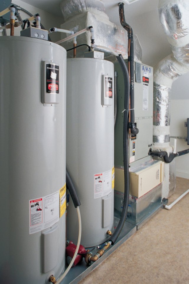
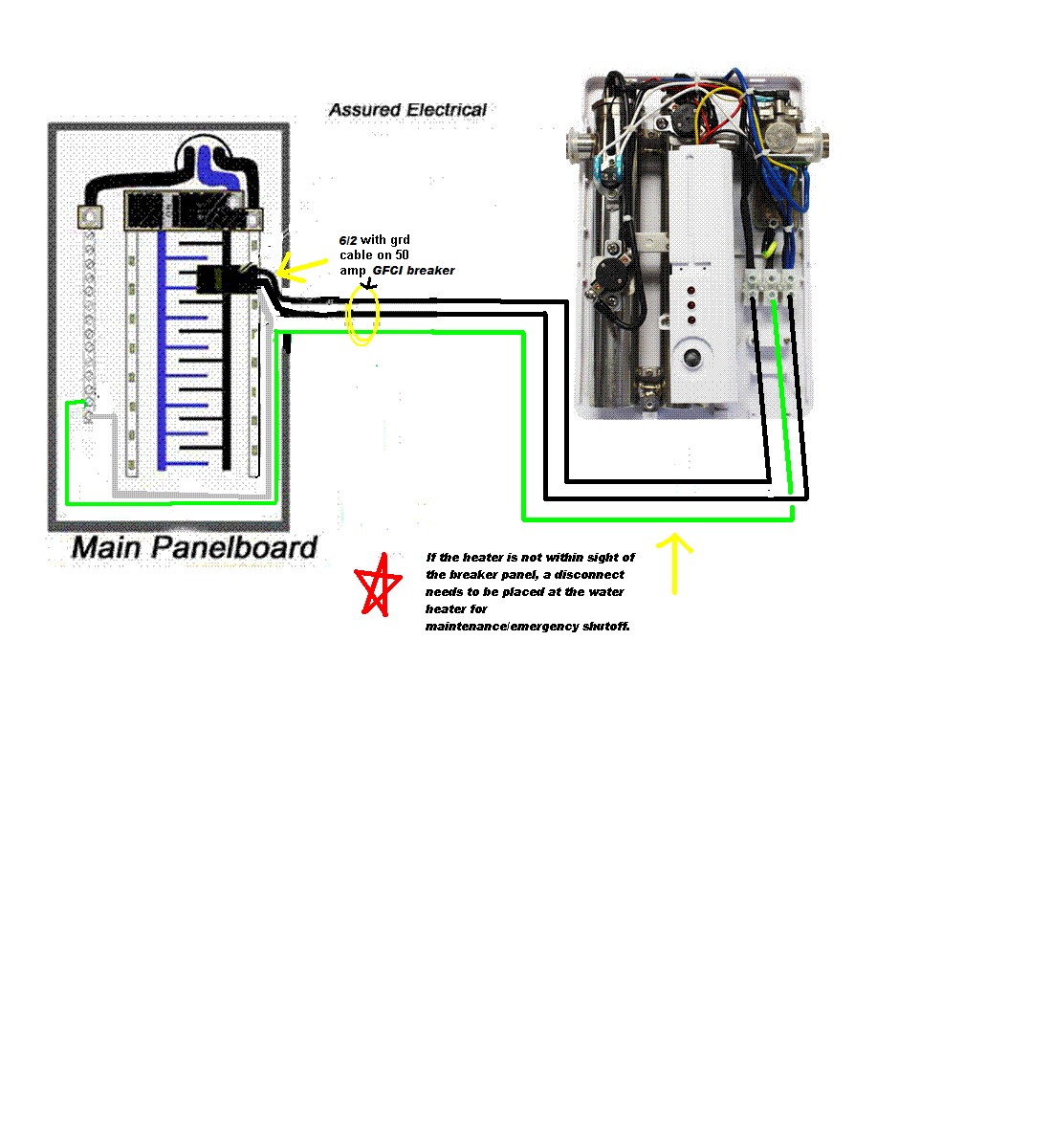
How to Wire a Hot Water Heater Using a Wiring Diagram | Hunker
Heater Selection – This diagram shows typical information that you will need when selecting a duct heater. Pilot Light Pilot lights are installed on the side panel and used to indicate heater conditions as follows: - heater energized - step energized - airflow switch open • Available with 24V or 120V control voltages Time Delay Relay

Wiring Diagram For Intertherm Mobile Home Air Handler With ...
The air flowing through the duct heater is heated in accordance with the following formula: P = Q × 0.36 × ∆t Installation The duct heaters can be installed in either a horizontal or a vertical duct. The air must flow through the duct heater in the direction of the arrow shown on the duct heater.
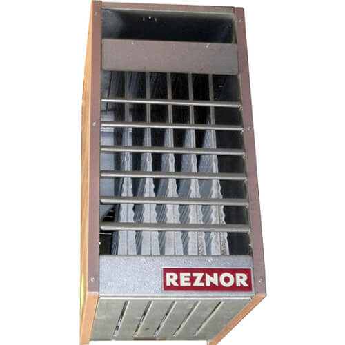
Reznor Heater Parts Diagram
fig. 4 - 15kw electric duct heater wiring diagram fig. 5 - 20kw electric duct heater wiring diagram 260 north elm street westfield, ma 01085 (413) 568-9571 • fax (413) 568-9613 7555 tranmere drive mississauga, ontario l5s 1l4 canada (905) 670-5888 • fax (905) 670-5782 fig. 3 - 10kw electric duct heater wiring diagram

Easy Installation Tutco Electric Duct Heater Automatic ...
WARREN TECHNOLOGY STOCK-LINE ELECTRIC DUCT HEATERS 1 1 12 20 8 8 12 9 7.25 be made to allow for adequate mixing of by-pass air and heater air to prevent stratification. SL10B 1 1 2 SL10T 3 SL15A* 3 ... • A specific wiring diagram is furnished for every heater regardless of the accessories.

Electric Car sign
Figure 1C SLIP-IN HEATER Step 1. Cut hole in side of duct 1/8" larger than heater body. Step 2. Insert heater until terminal box covers opening. Step 3. Secure heater in place with sheet metal screws. Figure 2C FLANGED HEATER Step 1. Provide flanges on ends of duct matching heater flanges Step 2. Secure heater flanges to duct flanges with sheet metal screws,

Goodman 10kw Heat Strip Wiring Diagram
National Electrical Code to eliminate shock hazard. Ambient temperatures must be considered when selecting wiring materials for electric heater circuits. Heating equipment and pro-cesses may cause associated wiring to operate well above ambient temperatures. These temperatures may result from heat conducted from the heater terminals, radiation from
240v Water Heater Wiring Diagram
Integral electric coils are available on Titus single duct and fan powered terminals. The heater design minimizes stratification and hot spots that can cause nuisance tripping of the thermal cutouts. Each complete terminal, with electric coil installed, is ETL listed and has been tested in accordance with UL standards.
Solar Space Heater
ELECTRIC HEATERS • O. & M. 6 ©March, 2007 Environmental Technologies FIELD WIRING NOTE: Prior to installing any wiring, check the unit name plate for main power voltage, control voltage and maximum overcurrent protection. Operating a heater at other than the specified voltage and phase can result in fire or electrical hazard.

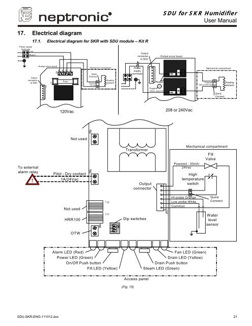
Neptronic Electric Heater Wiring Diagram - Wiring Diagram
Apr 10, 2018 · Warren Duct Heater Cbk Wiring Diagram Collection. July 30, 2018. April 10, 2018 by faceitsalon. Collection of warren duct heater cbk wiring diagram you are able to download at no cost. Please download these warren duct heater cbk wiring diagram by using the download button, or right visit selected image, then use Save Image menu. Wiring diagrams help technicians to view what sort of controls are wired to the system.

How to Install an Air Duct Damper | Smarthome Solution Center
electric water heater electric unit heater pipe trace heater resistance heater, kw shown ... duct smoke detector heat detector smoke detector horn & light designations (by e.c.) (by others) tt facp ann eol g ww pc ct ts t h tc ic f fc f t 1,3 or pm wm bd ufd b f s j j d wh ... submit product data, shop drawings, wiring diagrams, and descriptive ...

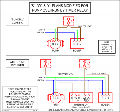
Lovely Wiring Diagram for Honeywell S Plan #diagrams # ...
Duct Heaters. 227 Series IOM. Electric Duct Heater Owner's Manual. Instructions for Electric Duct Heaters with Type 3R Terminal Boxes. User Manual - Process Air Heaters. Instructions for Field Replacement of Resistance Open Coil Elements in Brasch Duct Heaters. Unit Heaters. 233 Series IOM. 233 Series Core Replacement. 233 Series Pole ...

Wiring Diagram For Intertherm Mobile Home Air Handler With ...
of open coil and finned tubular duct heaters within minutes. With this software, your local INDEECO representative becomes the source for certified prints, wiring diagrams — complete submittal information. Our heaters and controls range from the simplest standard duct heater to the most sophisticated, custom designed comprehensive system.
110V - 480V G90 Plaka Elektrikli Hava Kanal Isıtıcılar OEM ...
Each electric duct heater's unique design allows air to flow freely for the lowest possible pressure drop. Our heaters are factory-assembled and wired for the electrical specialties and controls of each project, and are available with round duct connection collars. The heaters are shipped loose, can be duct-installed onsite and are designed
Nordyne Gas Furnace Wiring Diagram

Neptronic Electric Heater Wiring Diagram - Wiring Diagram

Air Conditioner Schematic | Air conditioner maintenance ...
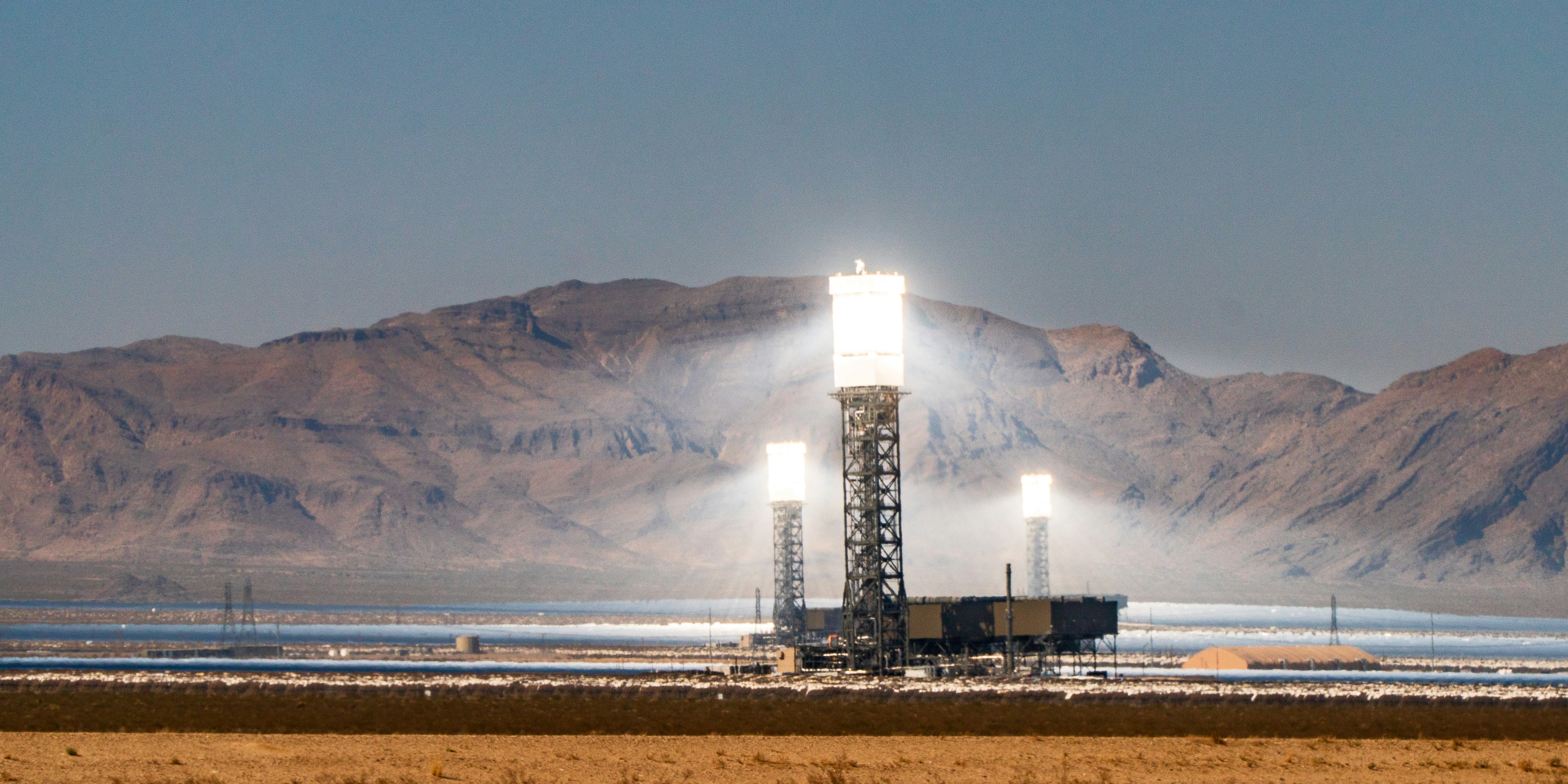
Ivanpah Solar Power Facility, Mojave Desert, October 2020

Hayward HeatPro | Pool Heat Pump Buying Guide | Chainsaw ...

Indeeco Duct Heater Wiring Diagram | Free Wiring Diagram
Neptronic Electric Heater Wiring Diagram - Wiring Diagram

Wiring Diagram For Intertherm Mobile Home Air Handler With ...

Reliant Heater Wiring Diagram - Complete Wiring Schemas

Wiring Manual PDF: 10kw Electric Heater Wiring Diagram
Modine Heater Thermostat Wiring Diagram
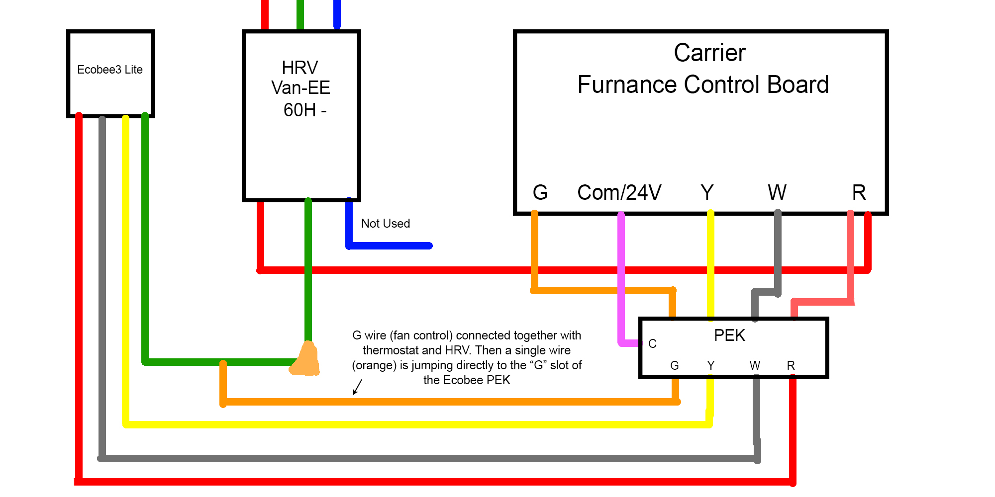
Hrv Wiring Diagram

Warren Duct Heater Cbk Wiring Diagram | Free Wiring Diagram

Control Panel | Tutco-Farnam

27,000 BTU Thermolec Electric Boiler 8KW, Boilers

Bathroom Vent Fan Wiring Diagram - BATHROOM DESIGN

Patent US8837922 - In-line duct supplemental heating and ...

Unique Honeywell Baseboard Heater thermostat Wiring ...

Indeeco Duct Heater Wiring Diagram | Free Wiring Diagram

Image from page 583 of "Electric railway journal" (1908)

3 Phase Heater Current Calculation - Smartvradar.com

Neptronic Electric Heater Wiring Diagram - Wiring Diagram


Comments
Post a Comment