39 Switch Loop Diagram
Ladder logic - Wikipedia Ladder logic is widely used to program PLCs, where sequential control of a process or manufacturing operation is required.Ladder logic is useful for simple but critical control systems or for reworking old hardwired relay circuits. As programmable logic controllers became more sophisticated it has also been used in very complex automation systems. How to Draw a Circuit Diagram - Edraw 17.2.2022 · Switch: An on-off switch allows current to flow only when it is in the closed (on) position. ... (AGC) circuit diagram. It is a closed-loop feedback regulating circuit used in an amplifier. It is most commonly seen in devices such as radio receivers and radar systems.
What Is A Switch Loop? light fixture and just the hot feed goes down to the switch and just the switch controlled hot wire comes back. This is called a switch loop (Diagram 2). Premade cables such as Romex are hard to find with both conductors colored. Here, both ends need to be marked with a band of black tape or stain. (Actually any color except green can be used.)
Switch loop diagram
View 2010 Dodge Journey Wiring Diagram Gif - easywiring A vehicle wiring diagram is a lot like a road map, according to search auto parts. View, print and download for free: Before you search for a. Luckily, there are some places that may have just what you need. Search in dodge journey 2010 1. Finding the Brake Light Switch on a 2010 Dodge Journey to from electrical - How should a switch loop be wired? - Home ... What you have is a switch loop, and is VERY common, especially in 50's and 60's homes. The white from the panel goes to the white from the fixture. This is the neutral. The black from the panel goes to the white from the switch. This is the feed. The black from the switch goes to the black from the fixture. This is the switched hot. Electrical: Switch loop with TWO light fixtures - OHW Here's how a normal single-light switch loop is set up: (light blue = white wire. You're supposed to have ground in there too, but I didn't want to try and squeeze it into the diagram.) Code for a switch loop allows you to use the white as a hot wire, but you have to tape it black on the ends to show that it's hot.
Switch loop diagram. learnmechanical.com › open-loop-and-closed-loop-systemOpen Loop and Closed Loop System -Working Diagram, Examples, PDF The closed-loop system is defined as Feedback from the output to the input is missing in the open-loop control system. To obtain More accurate Control, the controlled variable should be fed back and compared with the reference input. Instrumentation Loop Diagrams - InstrumentationTools The Loop diagram sometimes called a loop sheet. Loop Diagrams. Here we are discussing for the compressor surge control system (loop number 42):. Here we see that the P&ID didn't show us all the instruments in this control "loop." Not only do we have two transmitters, a controller, and a valve; we also have two signal transducers. Looping System Of Wiring - The Wiring In a switch loop, the hot and neutral wires arrive at the light fixture before reaching the switch. Cleat Wiring Methods of Electrical Wiring Systems w.r.t Taking Connection. The DB9 is also known as 9-pin D-sub, DB-9, DE-9, serial connector, RS232 connector or null modem connector. Light Switch Loop Wiring Diagram - U Wiring Wiring a switch loop diagram. To make a switch loop connect the incoming hot black wire to the white neutral wire that runs to the switch. Redline chevy 7 pin wiring harness wiring diagrams show. It shows three cables. A switch loop single pole switches light dimmer and a few choices for wiring a outlet switch combo device.
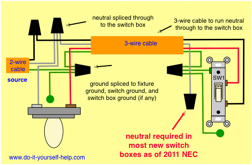
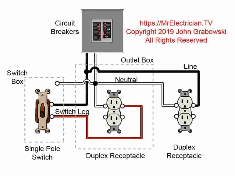
Switch Loops Figure 2 - Diagram of a switch loop The 2011 NEC code requires that the switch loop use wires of the proper color code to signify hot wires. A white wire signifies a neutral wire. From a physical wiring standpoint it will be necessary, at a minimum to run 14/3 cable which contains a black, red and white wire. Light Switch Wiring Diagrams - Do-it-yourself-help.com This diagram illustrates wiring for one switch to control 2 or more lights. The source is at SW1 and 2-wire cable runs from there to the fixtures. The hot and neutral terminals on each fixture are spliced with a pigtail to the circuit wires which then continue on to the next light. Wiring Diagram For Light Switch And Outlet In Same Box Light switch wiring diagram shows electrical power entering the ceiling light electrical box and then continues to a wall switch using a 3 conductor cable. A switch loop single pole switches light dimmer and a few choices for wiring a outlet switch combo device. For wiring in series the terminal screws are the means for passing voltage from one ... Light Switch Wiring Diagrams - Pinterest Jan 18, 2016 - Clear, easy-to-read diagrams for household electrical light switches with wiring instructions.
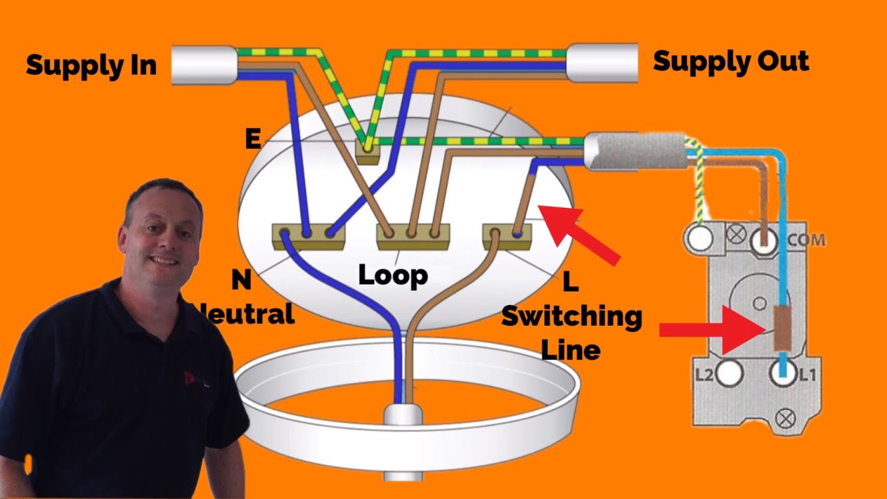
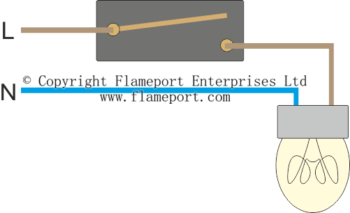
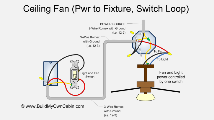
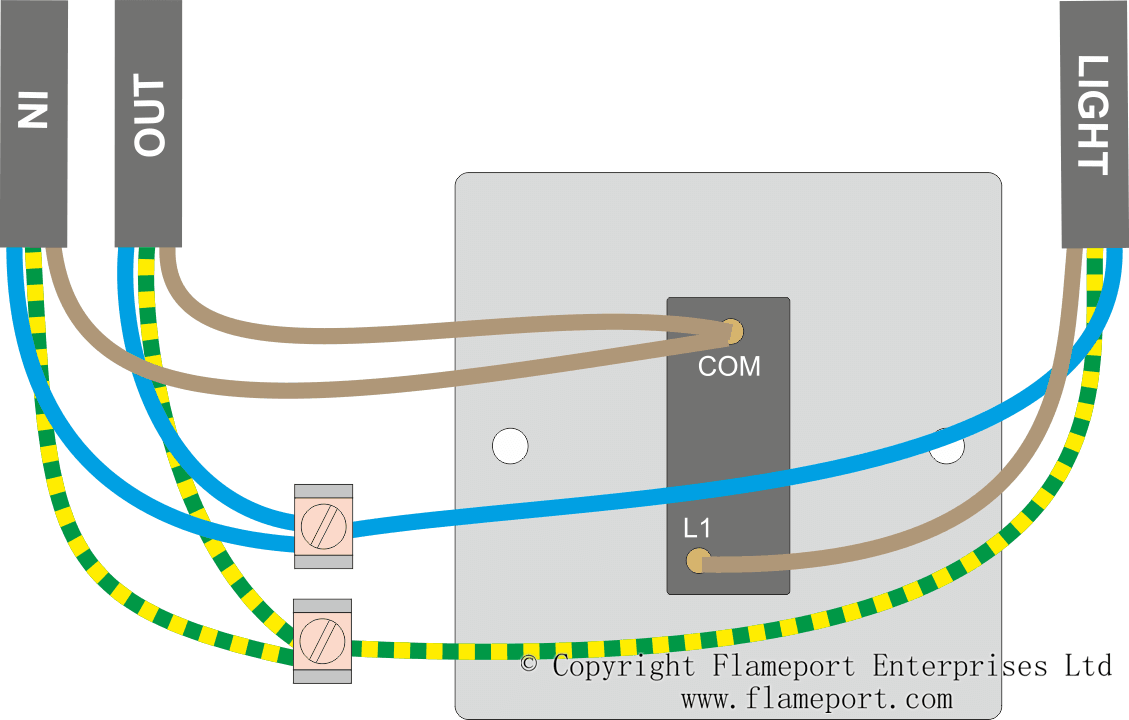
Ceiling Fan Wiring Diagram (Switch Loop) - Build My Own Cabin Ceiling Fan Diagram (Switch Loop) This ceiling fan wiring diagram can be used if the power source is supplied to the fan fixture. This wiring configuration is a bit limiting as the fan and light are controlled from a single switch. What is loop on a light switch? A switch loop is created when power is fed to a light fixture and the hot wire is broken and extended to a light switch. The neutral, white wire, which would not be used is simply capped off inside the electrical box. ... Instrument loop diagrams are also called instrument loop drawings or loop sheets. Each instrument bubble in a loop diagram ... Arduino Wiring Diagram Maker - U Wiring 8.11.2021 · Arduino Circuit Diagram Maker. Arduino Wiring Diagram Creator Posted by Margaret Byrd Posted on November 22 2019. Arduino Joystick Thumbstick Module Wiring Diagram Arduino Joystick Arduino Stepper To draw arduino circuit schematic drawing an diagram. Arduino wiring diagram maker. Circuitoios online circuit builder gives you wiring code and IoT solutions … Loop at Switch Lighting Circuits - Flameport Loop at the switch The principle is exactly the same as when looping at the ceiling rose or using a junction box. The 'in' cable supplies power from the previous light or consumer unit. The 'out' cable continues to the next light. The 'light' cable goes to the light fitting. There will only be three wires at the light - live, neutral and earth.
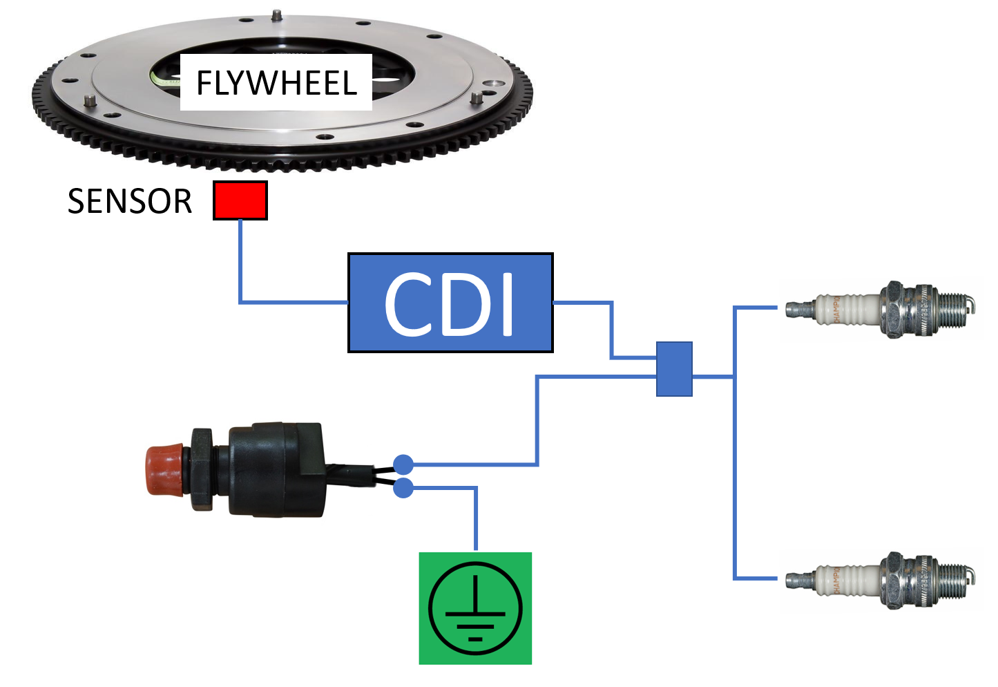
How To Fit A Kill-Switch | Boat Fittings
› article › light-switch-wiringLight Switch Wiring Diagram: A Complete Tutorial | EdrawMax Now you have to configure the switch in such a way that power comes from the light. You have to work with the white, black, and one bare wire coming from the box you configured above. Connect the loop of the bare wire in a hook shape to both box and the switch. Now, connect the loop of the black wire to the terminal at the bottom of the switch.
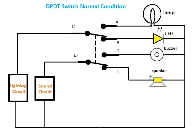
DPDT-Double Pole Double Throw, Working, Circuit Diagram ...
wiki.mikrotik.com › wiki › Manual:Switch_Chip_FeaturesManual:Switch Chip Features - MikroTik Wiki Warning: If you set mirror-source as a Ethernet port for a device with at least two switch chips and these mirror-source ports are in a single bridge while mirror-target for both switch chips are set to send the packets to the CPU, then this will result in a loop, which can make your device inaccessible.

Light Switch Wiring Diagrams - Do-it-yourself-help.com
What is a switch loop diagram? - AskingLot.com What is a switch loop diagram? Essentially a switch loop takes an incoming hot and neutral into the ceiling box, then passes the hot conductor through the box on the white conductor going down to the switch. From that switch box current travels on the black conductor back up to the ceiling box. Click to see full answer.
What Is A Switch Loop & How Does It Work?
Switch Loop Diagram - easywiring Switch Loop Diagram by Vallery Masson on May 20, 2021 In your switch box you should have one or more grounding conductors spliced together with a wire connector or wire crimp. A switch loop occurs when both the switch at the end of a circuit or an incoming cable and a neutral become hot leads and connect to a terminal.

Wiring | Electrical wiring, Light switch wiring, Diy electrical
Effects Loop Switch Boxes - General Guitar Gadgets Effects Loop Switch Box Application Diagrams. Here is a diagram example showing the use of the Effects Loop Switch Box. The box is used to switch in or out a "loop" of guitar effect pedals. Very useful in may rigs. Especially useful if you want to switch on several effects with one press of a foot switch.

Need help adding a ceiling fan to a "switch loop" circuit ...
What Is A Switch Loop & How Does It Work? - Livinator The switch loop is an integral part of your home; another way of describing it is as a connection between your light and a switch, allowing you to turn it on and off at will without removing the bulb. This loop can be used to create one switch or several switches; all operating the same light.

Color online) A schematic of the fiber-loop switch based on ...
Episode 13 - SCHEMATICS how a switch loop works - YouTube 00:00 Intro01:33 Schematics on how a switch loop works08:24 Layout in detail08:46 OutroFor those of us that are more visual learners, I've made this show one...

Wiring Diagram 2 Way Switching of a Lighting Circuit Using the 3 Plate Method Connections Explained
What is Layer 2 Switching loop - OmniSecu To understand Layer 2 Switching loop, refer the following diagram. A Ethernet frame originating from Workstation to the File Server, first reaches the Switch 4. Switch 4 will forward the packet to all its ports (except the source port) since the MAC address of the destination device (File Server) may not be available in its MAC address table ...

Light Switch Wiring Diagrams - Do-it-yourself-help.com
Wiring Diagrams for a Switched Wall Outlet - Do-it ... Wiring an Outlet to a Switch Loop This wiring diagram illustrates adding wiring for a light switch to control an existing wall outlet. The source is at the outlet and a switch loop is added to a new switch. The hot source wire is removed from the receptacle and spliced to the red wire running to the switch.
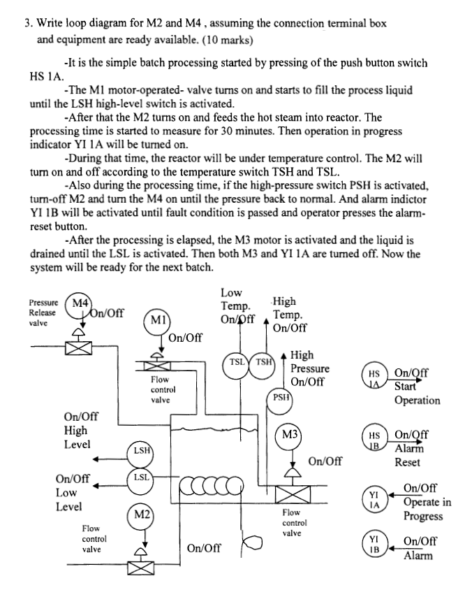
3. Write loop diagram for M2 and M4, assuming the | Chegg.com
ImproveNet Helping you plan your home improvement project, from start to finish

Episode 13 - SCHEMATICS how a switch loop works
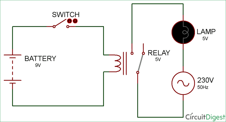
fusesdiagram.comFuses box diagram Passing through an overcurrent loop usually results in short circuit. Relay – an electrical device (switch) designed to close and open various sections of electrical circuits for specified changes in electrical or non-electrical input quantities.

What is it called when 2 light switches control 1 light? - Quora
› tag › 2-way-switch-wiring-diagram2 way switch wiring diagram - light wiring There is a chance that if your house has these old wiring colours the switch drops may be from a loop-in-loop-out radial lighting circuit done with junction boxes rather than ceiling roses as shown in Fig 2. The switch wiring is all the same but the switch wire (cable C) leads up to a different set up.
Just replaced light fixture, now switch won't turn it off. 3 ...
PDF P&IDs AND LOOP DIAGRAMS - Integrated P&IDs AND LOOP DIAGRAMS P&IDs and loop diagrams are construction and documentation drawings that depict the flow of the process and illustrate the instrumentation control and measurement interactions, wiring and connections to the process. The process is illustrated in sections or subsystems of the process called loops. A loop diagram will ...
Electrics:Single way lighting
Understanding Multiple Spanning Tree Protocol (802.1s) - Cisco 17.4.2007 · This diagram shows the logical topology of the IST instance: Switch B receives two BPDUs for instance 0 from Switch A (one on each port). It is clear that Switch B has to block one of its ports in order to avoid a loop.
Wiring Diagram 2 Way Switching of a Lighting Circuit Using ...
› what-is-an-open-loop-controlOpen Loop Control System : Block Diagram, Working & its ... The open-loop control system block diagram is shown below. In the following diagram, the input can be given to the control system so that the required output can be obtained. However, this obtained output cannot be considered using this system for additional reference input.
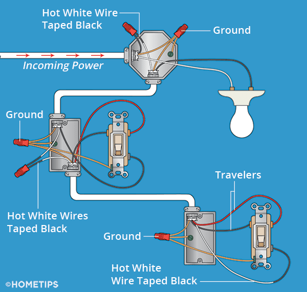
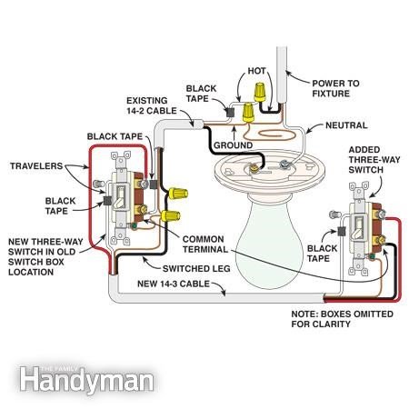
Three-Way Switch Wiring | How to Wire 3-Way Switches - HomeTips
Episode 12 - How To Wire For A Switch Loop - YouTube 00:00 Intro03:10 Rolling out wire to begin06:12 Joining grounds together09:42 Hooking up switch12:56 Competed switch loop13:40 OutroThis episode is something...
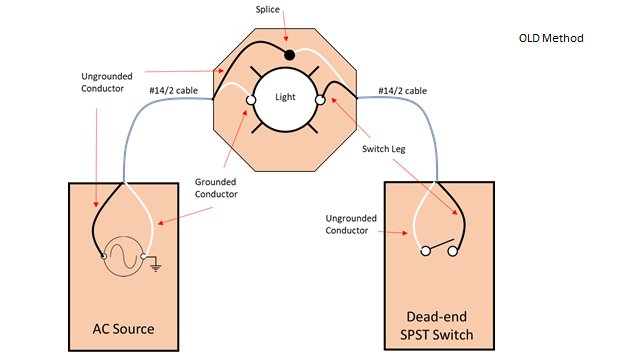
Dead-end switch loops – Basic Lighting for Electricians: Level 1
› case-statement-in-javaCase Statement in Java | Flow diagram of Switch-Case ... Flow Diagram of Switch Case Statement. The above flow diagram clearly shows how the Switch and Case statement works in Java. It shows how matching the expression defined in the Switch statement is matched with the Case value starting from the top until the last steps.

SOLVED: Switch loop with mutiple fixtures - Fixya
Switch Loop Diagram - Diagram Sketch Switch Loop Diagram. angelo on October 2, 2021. Switch Loops Light Switch Wiring Home Electrical Wiring Switch . Mute Switch Spst Normally Open Toggle Wiring Diagram Guitar Pedals Electronics Basics Guitar Diy . True Bypass Loop Schematics Wiring Diagrams Diy Guitar Pedal Guitar Pedals Guitar Diy .
Circuits: One Path for Electricity - Lesson - TeachEngineering
Arduino - Stepper Motor and Limit Switch | Arduino Tutorial Learn how to stop a stepper motor when the limit switch is touched. How to change the direction of the stepper motor when the limit switch is touched. How to use the limit switch, stepper motor, and Arduino. The detailed instruction, code, wiring diagram, video tutorial, line-by-line code explanation are provided to help you quickly get started with Arduino.
Lighting Circuit diagrams for 1,2 and 3 way switching
Wiring A Switch Loop Diagram - U Wiring Wiring a switch loop diagram. A switch loop single-pole switches light dimmer and a few choices for wiring a outlet switch combo device. Also included are wiring arrangements for multiple light fixtures controlled by one switch. This page contains wiring diagrams for household light switches and includes.

Wiring a Switch Loop - Fine Homebuilding
Switch Loop Wiring Diagram - easywiring Switch loop wiring diagram. The hot source wire is removed from the receptacle and spliced to the red wire running to the switch. Circuit electrical wiring enters the switch box. Also included are wiring arrangements for multiple light fixtures controlled by one switch two switches on one box and a split receptacle controlled by two.
Simple Relay Switch Circuit Diagram
Electrical: Switch loop with TWO light fixtures - OHW Here's how a normal single-light switch loop is set up: (light blue = white wire. You're supposed to have ground in there too, but I didn't want to try and squeeze it into the diagram.) Code for a switch loop allows you to use the white as a hot wire, but you have to tape it black on the ends to show that it's hot.

Adding wall switch and another ceiling light (switch loop ...
electrical - How should a switch loop be wired? - Home ... What you have is a switch loop, and is VERY common, especially in 50's and 60's homes. The white from the panel goes to the white from the fixture. This is the neutral. The black from the panel goes to the white from the switch. This is the feed. The black from the switch goes to the black from the fixture. This is the switched hot.
How to Wire a 3-Way Switch: Wiring Diagram - Dengarden
View 2010 Dodge Journey Wiring Diagram Gif - easywiring A vehicle wiring diagram is a lot like a road map, according to search auto parts. View, print and download for free: Before you search for a. Luckily, there are some places that may have just what you need. Search in dodge journey 2010 1. Finding the Brake Light Switch on a 2010 Dodge Journey to from
Ceiling Fan Wiring Diagram (Switch Loop)
What Is A Switch Loop?
Loop at Switch Lighting Circuits
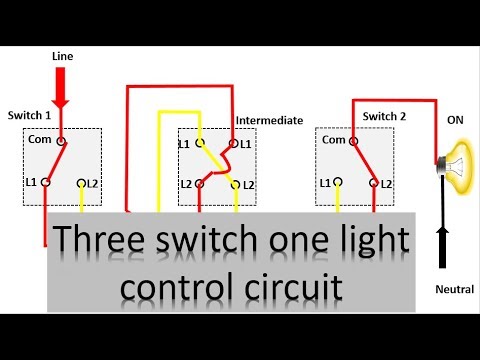
3 switch one light control diagram | three way lighting circuit | Earth Bondhon
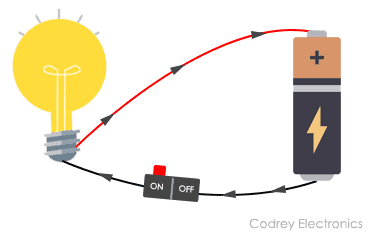
What is an Electrical Circuit? - Codrey Electronics
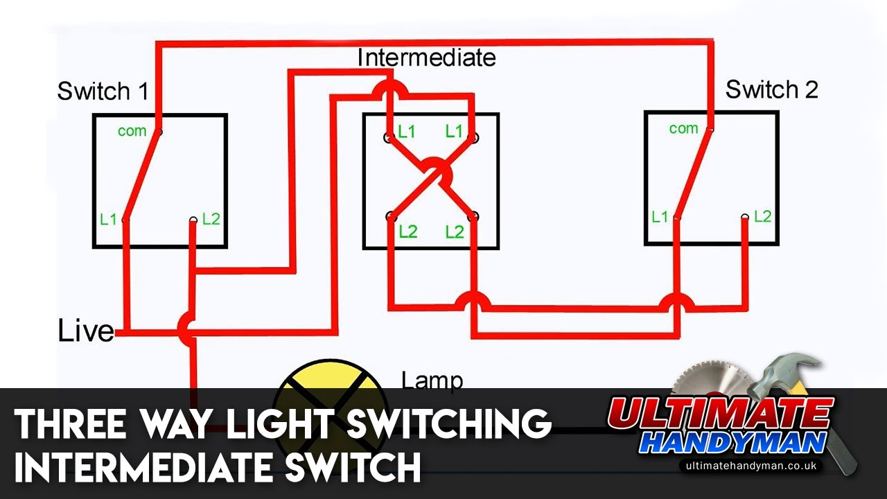
Three way light switching | Intermediate switch
What Is A Switch Loop & How Does It Work?

Light Switch Wiring Diagrams - Do-it-yourself-help.com

Switch Loops
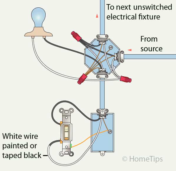
Standard Single-Pole Light Switch Wiring - HomeTips
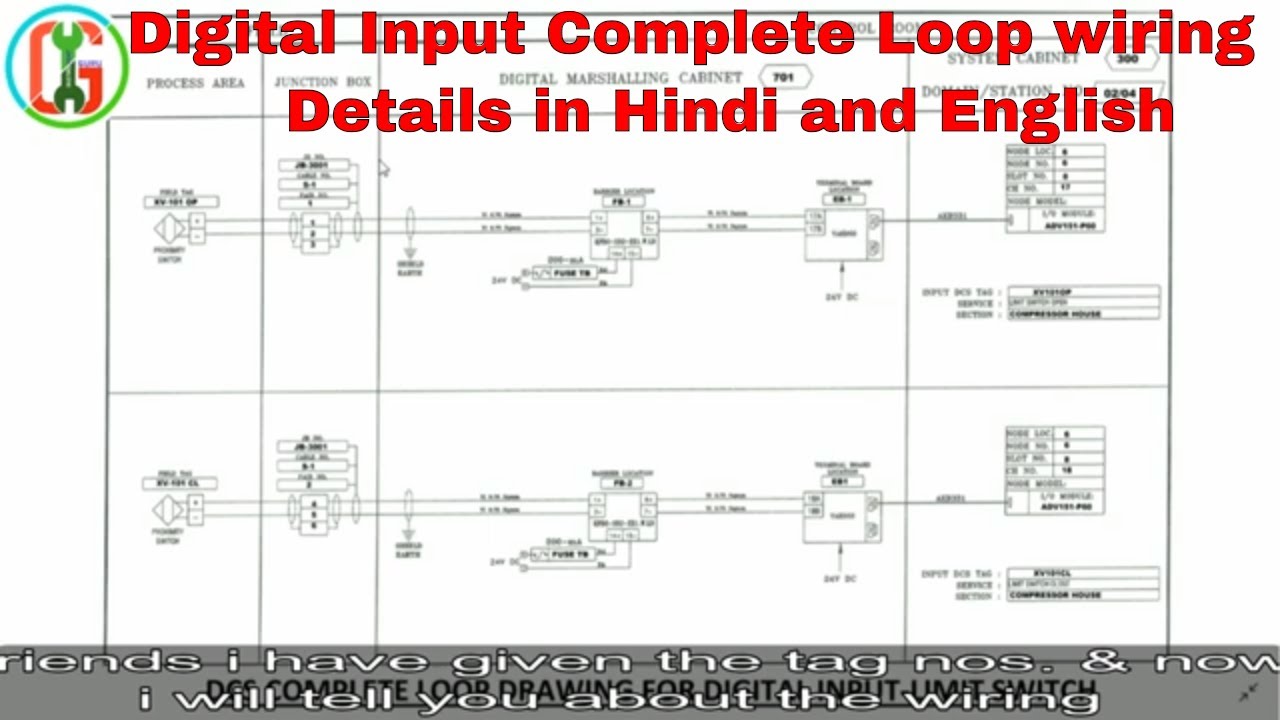
Digital Input Limit Switch Complete Loop in Hindi & English

Light Switch Wiring Diagrams - Do-it-yourself-help.com
Switched Outlet Wiring Diagrams

Resources

How a 2 Way Switch Wiring Works? | Two-Wire and Three-Wire ...


Comments
Post a Comment