43 120 to 24 volt transformer wiring diagram
PDF Acme Electric - Dry-Type Distribution Transformers ... GENERAL ELECTRICAL CONNECTION DIAGRAMSACME® TRANSFORMER™ WIRING DIAGRAMS PRIMARY: 240 X 480 SECONDARY: 120/240 TAPS: None X4X1 H4 H3H2 H1 X2 X3 PRIMARY: 240 X 480 SECONDARY: 120/240 12, 2 /2% ANFC, 4, 2 1/2% BNFC X4 X1 H10 H2 H3 H1 X2 X3 H5 H6 H4 H7 H8 H9 Connect Connect Primary Primary Inter- Secondary Volts Lines To Connect Lines To 216 H1-H10 H1 to H9 H10 to H2 480v 3 Phase To 120/240v Single Phase Transformer Wiring ... Application Notes Electronic Components Datasheet PDF Search Engine. X1 X4 or X2 X4. The wiring diagram was scratched up and. Any two wires of the 240V 3-phase developed by the secondary of the transformer may be used to. 480v to 120v transformer wiring diagram elegant 3 phase step down.
480v To 120v Control Transformer Wiring Diagram on 480v To 120v Control Transformer Wiring Diagram. Why use a Control Power Transformer? The schematic symbol for the transformer is represented by two groups the main motor circuit operates at V, while the control circuit is at V. Control Circuit Wiring of CPTs.

120 to 24 volt transformer wiring diagram
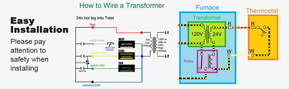
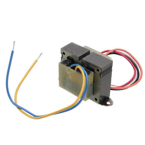
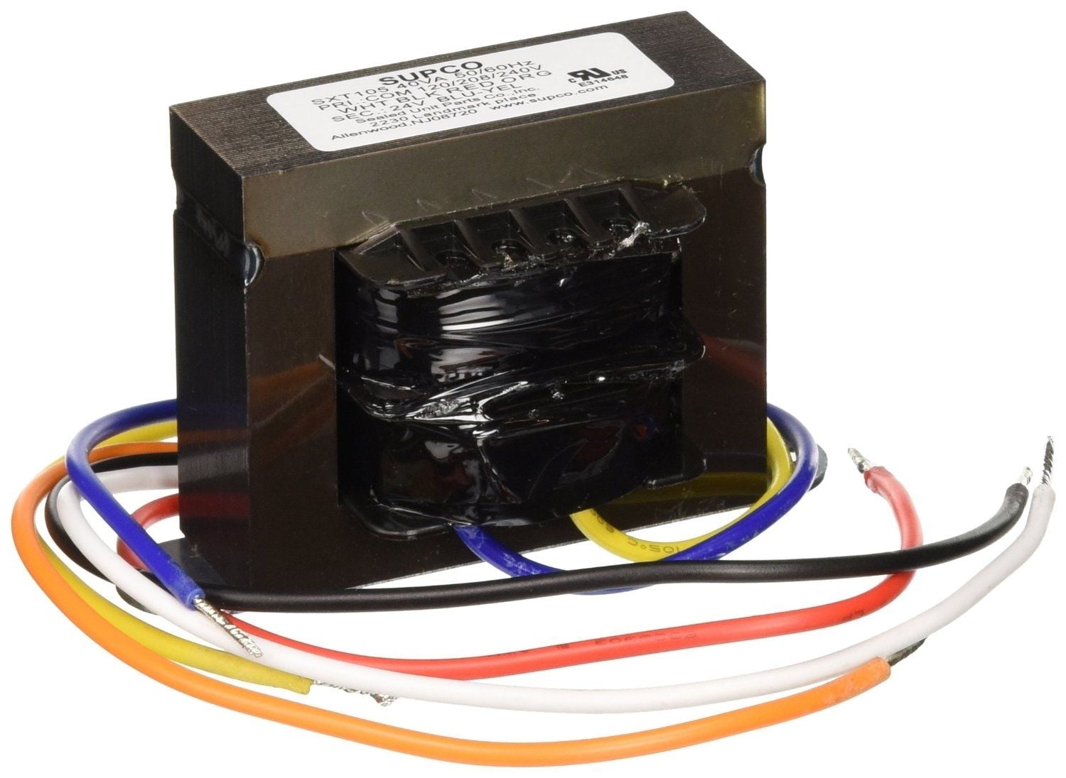
How to Wire a 24V Transformer - Hunker Step 1. Inspect the wires connected to the 24 VAC transformer. There are usually four wires--two black and two more that are yellow, green or blue. The two black wires will be connected to the 120 VAC input, while the yellow, green or blue wires are the 24 VAC output. PDF 120/208/240 to 24VAC Transformer (Supplied) 3. Connect the wires above to the relay per the wiring diagram, Figure 1. 4. Connect the wires from the HALO-LED to the supplied transformer per Figure 1. 5. Connect AHU Line 2 to the supplied transformer according to the unit voltage. HALO-LED Condenser Common/ TStat Common Yellow wire from AHU Condenser Contactor-Power 120/208/240 to 24VAC ... Bucking 208v To 240v Wiring Diagram Connect using wiring diagram #7 in Buck & Boost literature Warning: Three phase 4-wire loading requires a 3-phase 4-wire primary source for wiring diagram. 16/32, or 24/48 (depending on the model) use the wiring diagram located on the If you are using this unit as an auto transformer to buck (lower) or boost (raise) the B.
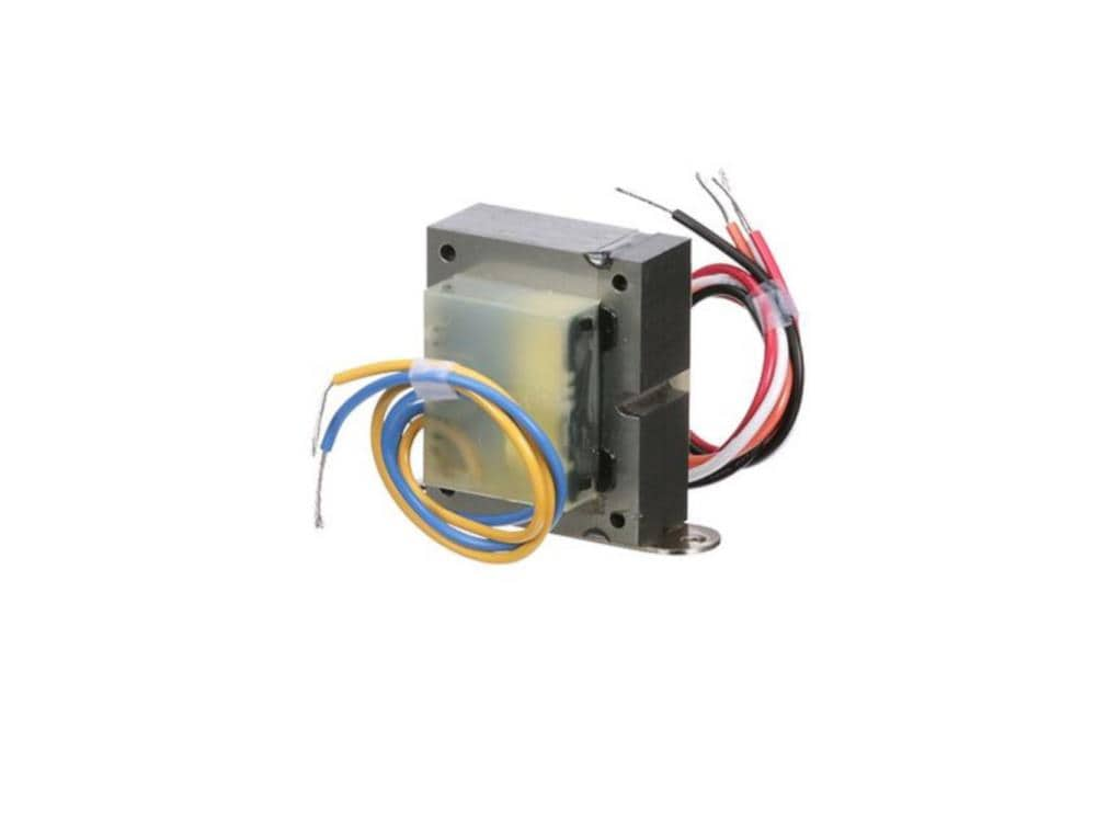
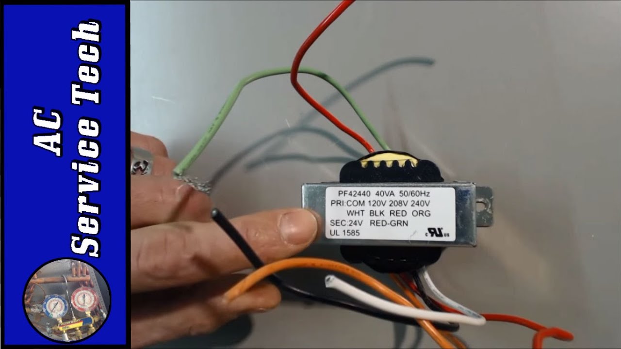
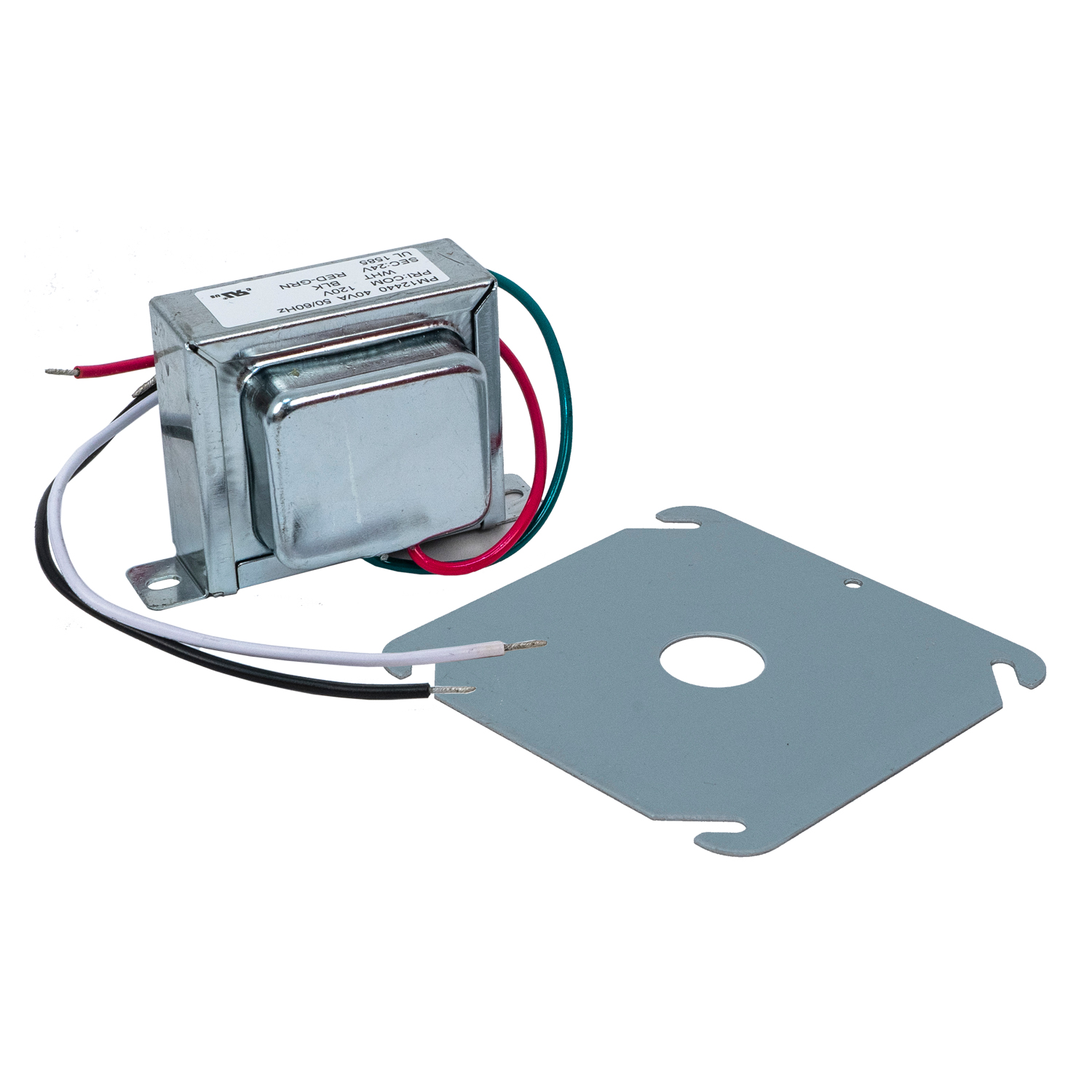
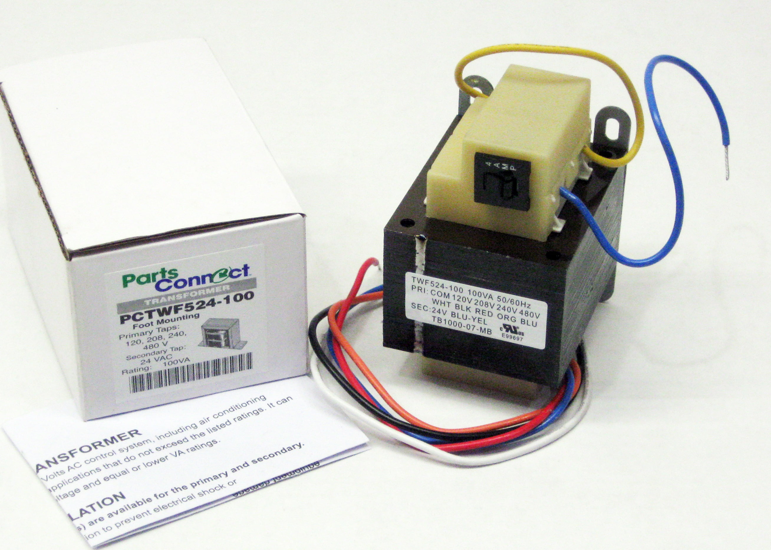
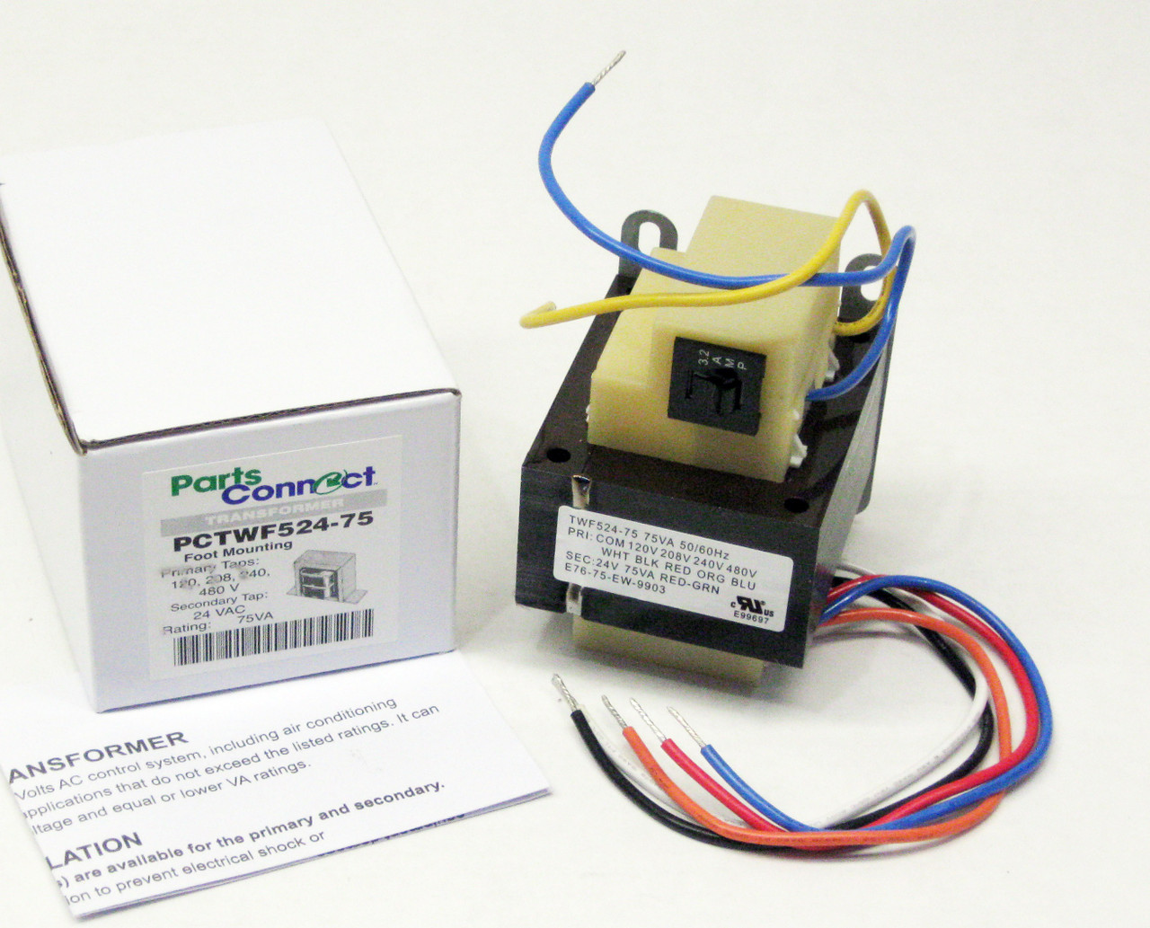
120 to 24 volt transformer wiring diagram. 120 Volt to 24 Volt Transformer Wiring Diagram - autocardesign 120 Volt to 24 Volt Transformer Wiring Diagram - wiring diagram is a simplified okay pictorial representation of an electrical circuit. It shows the components of the circuit as simplified shapes, and the talent and signal links surrounded by the devices. PDF Buck-boost Transformer Installation Sheet BUCK-BOOST TRANSFORMER INSTALLATION SHEET 004-0921-000_0816 Buck-Boost Installation Sheet jeffersonelectric.com 1 of 4 If you are using this unit as an isolation transformer with a primary of 120 or 240 or 480 volts and the secondary of 12/24, 16/32, or 24/48 (depending on the model) use the wiring diagram located on the inside of the cover to the wiring Foot Mount Transformer Primary 120/208/240V Secondary 24 ... Foot Mount Transformer Primary 120/208/240V Secondary 24 Volts V.A.Rating 40VA. Packard. Item ID: PF42440. Purchase options: Sales Unit: Each. Case Quantity: 30. Pallet Quantity: 1080. When ordering per case, enter the total number of pieces in the quantity field. For example, if one case has 30 pieces and you want 2 cases enter 60 in the ... 12-0-12 Centre Tapped Transformer: Wiring, Specifications ... These are the input wires for the transformer, it is connected to the phase and neutral of AC mains. 2. T1 and T3. There are the output terminals of the Transformer, the voltage across it will be 24V AC. 3. T2. This is the centre tapped wire of the transformer; this wire can be combined with either T1 or T3 to get 12V AC across it.
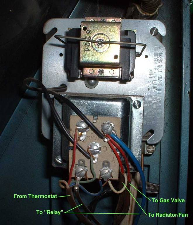
Wiring 480/240V to 240/120V on Epoxy Resin Encapsulated ... Wiring 480/240V to 240/120V on Epoxy Resin Encapsulated Transformers | Schneider Electric Support - YouTube. Wiring 480/240V to 240/120V on Epoxy Resin Encapsulated Transformers | Schneider ... PDF Wiring Diagram Using a Zone Valve with a 24-V Thermostat ... Wiring Diagram Using a Zone Valve with a 24-V Thermostat and a Transformer For illustration purposes only: • Location of thermostat may vary. White Black R 110-V Power Source 24-V Thermostat (p/n 8200008) RC Y B O RH G W Zone Valve Unit Bypass Main - Back to Outdoor Furnace C W R C NOTE Thermostats must be installed by quali˜ed technician ... PDF Wiring Diagrams - AutomationDirect If you have any questions regarding these wiring diagrams or are having any difficulty correctly installing our transformers, please contact HPS customer service or technical support in the U.S. at 1-866-705-4684 or in Canada at 1-888-798-8882. HPS Imperator tm Industrial Control Transformer Wiring Diagrams Issue Date: October 2007 rev4 Page 1 of 9 120 to 24 transformer wiring | Electronics Forum (Circuits ...
480 Volt to 120 Volt Transformer ... - Wiring Diagram Sample Name: 480 volt to 120 volt transformer wiring diagram - Booster Transformer 600v To 480v Single Phase Three Pdf Types And 480V 120V Wiring Diagram; File Type: JPG; Source: teenwolfonline.org; Size: 249.01 KB; Dimension: 1275 x 1654 480 input 240/120 output control transformer wiring mystery The "control" transformers are quite available, Hammond HPS (Hammond Power Solutions) makes a lot of them. As for teh 120/240 vs 120 OR 240, there is NO difference. For 120/240, you wire the X2 and X3, etc just as for 240V, but you get the voltages as Thermite has mentioned. How to Test a 24 Volt Transformer - Hunker There are two sides to the 24-volt transformer: A high side and a secondary - or low-voltage - side. The high side is the line-voltage of the transformer and the electrical connection to the feeding voltage, generally a 120-VAC power. The secondary or low-voltage side is the power that is transformed into 24 volts. 480 Volt Transformer Wiring Diagram - Wiring Tech In 480 to 24 volt transformer wiring diagram, 480 volt 3 phase to 240 volt 3 phase transformer wiring diagram, 480 volt 3 phase transformer wiring diagram, 480 volt single phase transformer wiring diagram, 480 volt three phase transformer wiring diagram, 480 volt to 120 volt transformer wiring diagram, 480 volt to 240 120 volt transformer wiring diagram, 480 volt to 240 volt single phase transformer wiring diagram

Help Installing Nest on Millivolt System Using 24v ...
need help wiring 240v -> 24v transformer for RPC start ... I am trying to get a start circuit in my RPC and have a pri 208/240v sec 24v transformer and 24v contactor. The transformer has line markings - c (common) 208 240. I understand 208 is 3 phase so don't use, but the common and 240 has me stumped. First I thought 240 did not use common, second, to get 240 you need 2 120v lines.

Universal Transformer 120/208/240v to 24v 40 watt
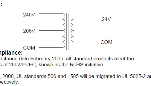
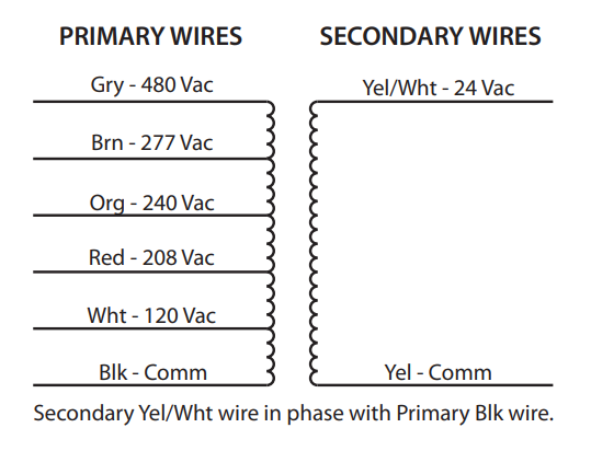
PDF Connecting a multi-tap transformer for 24 volt output. It should be from 24 to 28 volts. 2. Check this wiring diagram against the wiring diagram supplied with the transformer. The color of the wires may be different. 3. The general rule is that the more winding that is connected on the primary, the lower the secondary voltage. Examples: a) 120 volts connected to the Black & Red wires provides only 12 volts at the secondary.

Installation – Sunpak Patio Heaters
45 Kva Transformer Wiring Diagram Gallery - Wiring Diagram ... Name: 45 kva transformer wiring diagram - Awesome 480v To 120v Transformer Wiring Diagram Luxury Pretty 24v Transformer Wiring Diagram Gallery Wiring Diagram; File Type: JPG; Source: latinopoetryreview.com; Size: 157.85 KB; Dimension: 800 x 600

Protactor Universal Furnace Transformer 115-208-240 Volt ...
PDF 69-1641EF 01 - AT20, AT40, AT72D, AT87, AT88 AT Transformers transformer. All wiring must comply with local electrical codes and ordinances. Tape all unused exposed leadwires separately. 2. Connect primary leadwires to line voltage power supply. See Fig. 11 through 13. 3. Connect transformer seco ndary leadwires to 24 Vac control system. Fig. 11. AT20/AT40 Transformer schematic. Fig. 12.
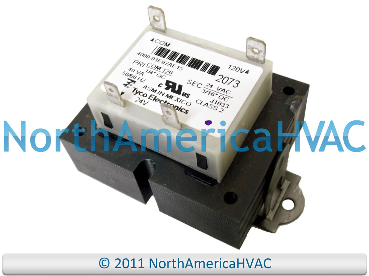
Control Transformer 40VA, Primary 120, 208, 240V Secondary ...
PDF Aprilaire Humidifier Wiring Diagrams - Alpine Home Air 24 Vo lt 120-24 Vo lt Tr ansformer 24 Vo lt 120V Hot To 120V Power This configuration allows the humidifier to run only when there is a call for heat. Refer to your furnace's manual for the voltage on the "HUM" terminal. This diagram indicates the "HUM" terminal is 115 volts. Diagram #4 Aprilaire Automatic Humidifier Wiring

Uhppote - 24v 40va Thermostat Doorbell Transformer Power ...
PDF Switching Relay Wiring Diagrams 120 Volts Switching Relay Wiring Diagrams ZONE 1 ZONE 2 ZONE 3 FUSE 1 AMP Z ONE 1 ZONE 2 ZONE 3 POWER ZONE 1 ZONE 2 N P ZC H X1 X2 R ... 120 Volts 120v 24v Boiler Connections T 1 T 2 3 Zone Valve Hot Neutral Wiring for Zone Valve ... Transformer Thermostat Burner TV T Z C1 C2 L1 L2 B1 B2 120 Volt Boiler Circulator L8124E R H
503 Series Foot Mount Transformer 120/208/240 to 24V 40VA
480 To 120/240 Transformer Wiring - Wiring Diagram Pictures Transformer To Wiring ImageResizerTool Com November 23rd, - to transformer wiring diagram as well as.GENERAL ELECTRICAL CONNECTION DIAGRAMSACME® TRANSFORMER™ WIRING DIAGRAMS PRIMARY: X SECONDARY: / TAPS: None X4X1 H4 H3H2 H1 X2 X3 PRIMARY: X SECONDARY: / 12, 2 /2% ANFC, 4, 2 1/2% BNFC X4 X1 H10 H2 H3 H1 X2 X3 H5 H6 H4 H7 H8 H9 Connect Connect Primary Primary Inter- Secondary Volts Lines To Connect Lines To H1.
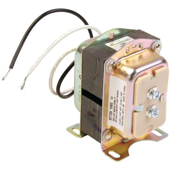
Honeywell Home 24-Volt Transformer AT72D
Compressor Pressure Switch Wiring Diagram - easywiring Compressor pressure switch wiring diagram. Electrical code and local regulations. If you are well grounded the power in a 120 vac circuit can kill you. Pressure switch wiring diagram air compressor and 2013 05 28 in pressure switch wiring diagram air compressor image size 1024 x 721 px and to view image details please click the image.
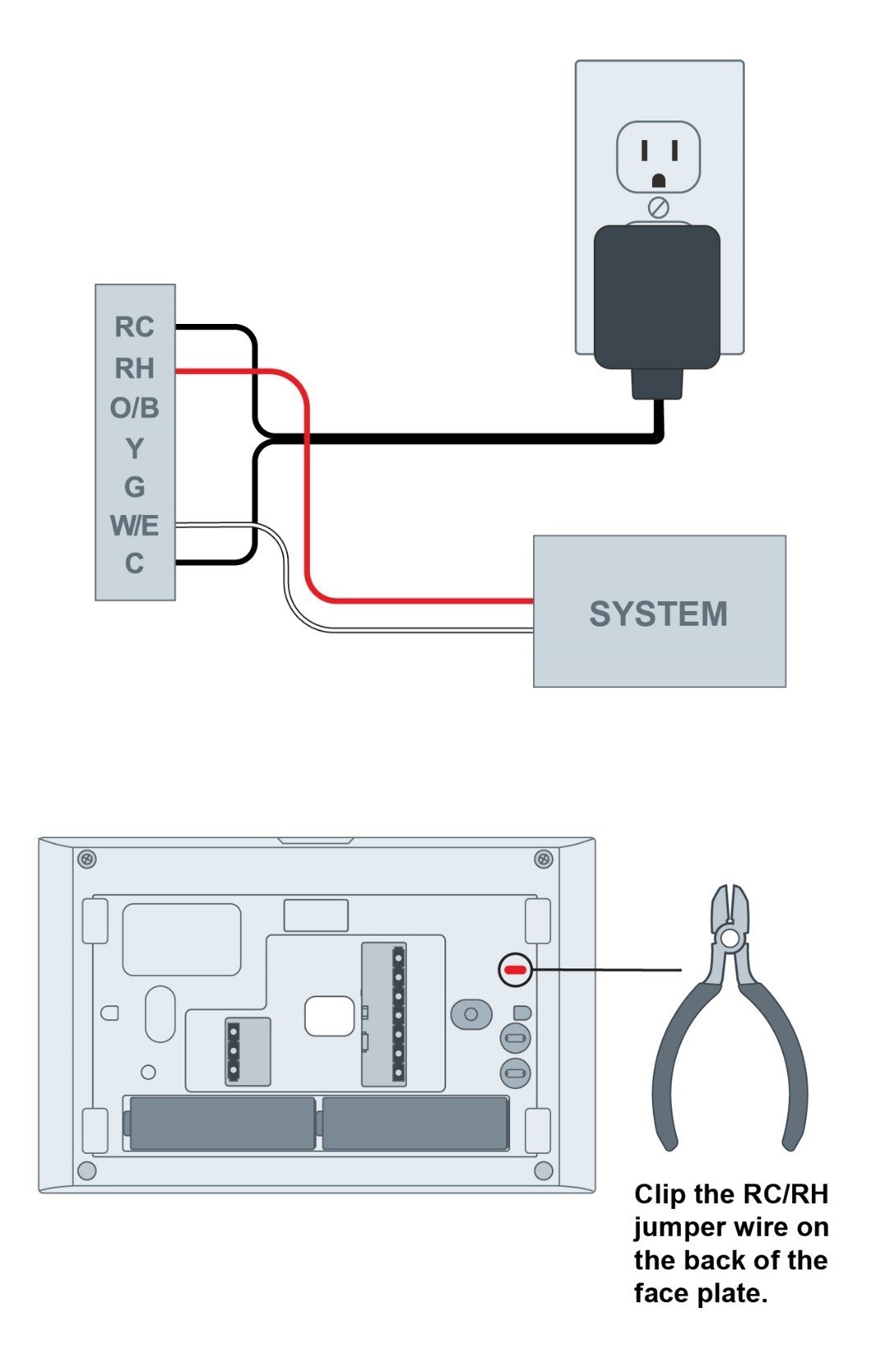
Adding 24 VAC External Transformer in Place of C wire | Sensi US
480v 3 Phase To 120 240v Transformer Wiring Diagram ... Wiring diagram 480 120v potential of control power transformer for basics information guide grounding transformers step up down and isolation 2019 3 phase 240 to n 0060 1021 230 vac ge catalog section 15 practical machinist largest 208v 240v single connections xfmr dry 1ph 25kva 240x480v 120. 480V To 240V Transformer Wiring Diagram 240v to 480v ...

2. Introduction
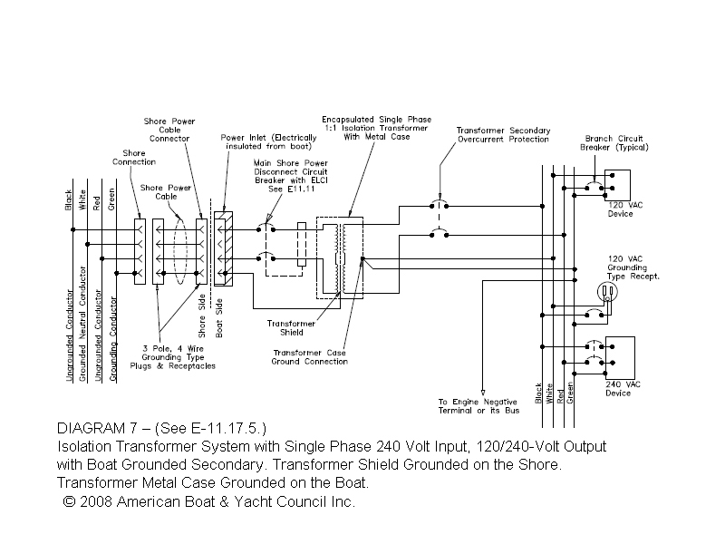
PDF Buck-Boost Transformer Installation Sheet - AutomationDirect Buck-Boost Transformer Installation Sheet Revised on April, 2011 by T.E. If you are using this unit as an isolation transformer with a primary of 120 or 240 or 480 volts and the secondary of 12/24, 16/32, or 24/48 (depending on the model) use the wiring diagram located on the inside of the cover to the wiring compartment.

I have a 120V duct booster fan, a 24V thermostat, a 6AZT9 ...
PDF Electrical Connection Diagrams Acme Transformer Design Figures GENERAL ACME® TRANSFORMER™ WIRING DIAGRAMS PRIMARY: 120 x 240 SECONDARY: 120/240 TAPS: None X4 X1 H4 H3 H2 H1 X2 X3 ConnectConnect Primary Primary Inter- Secondary Volts Lines To Connect Lines To 240 H1-H4 H2 to H3 120 H1-H3 & H2-H4 Secondary Volts 240 X2 to X3 X1-X4 120/240 X2 to X3 X1-X2-X4 120 X1 to X3 X1-X4 X2 to X4 PRIMARY: 600

Using Potential Transformers - Continental Control Systems, LLC
Bucking 208v To 240v Wiring Diagram Connect using wiring diagram #7 in Buck & Boost literature Warning: Three phase 4-wire loading requires a 3-phase 4-wire primary source for wiring diagram. 16/32, or 24/48 (depending on the model) use the wiring diagram located on the If you are using this unit as an auto transformer to buck (lower) or boost (raise) the B.
White-Rodgers Transformer, 120 Volt to 24 Volt, 40VA, 90 ...
PDF 120/208/240 to 24VAC Transformer (Supplied) 3. Connect the wires above to the relay per the wiring diagram, Figure 1. 4. Connect the wires from the HALO-LED to the supplied transformer per Figure 1. 5. Connect AHU Line 2 to the supplied transformer according to the unit voltage. HALO-LED Condenser Common/ TStat Common Yellow wire from AHU Condenser Contactor-Power 120/208/240 to 24VAC ...
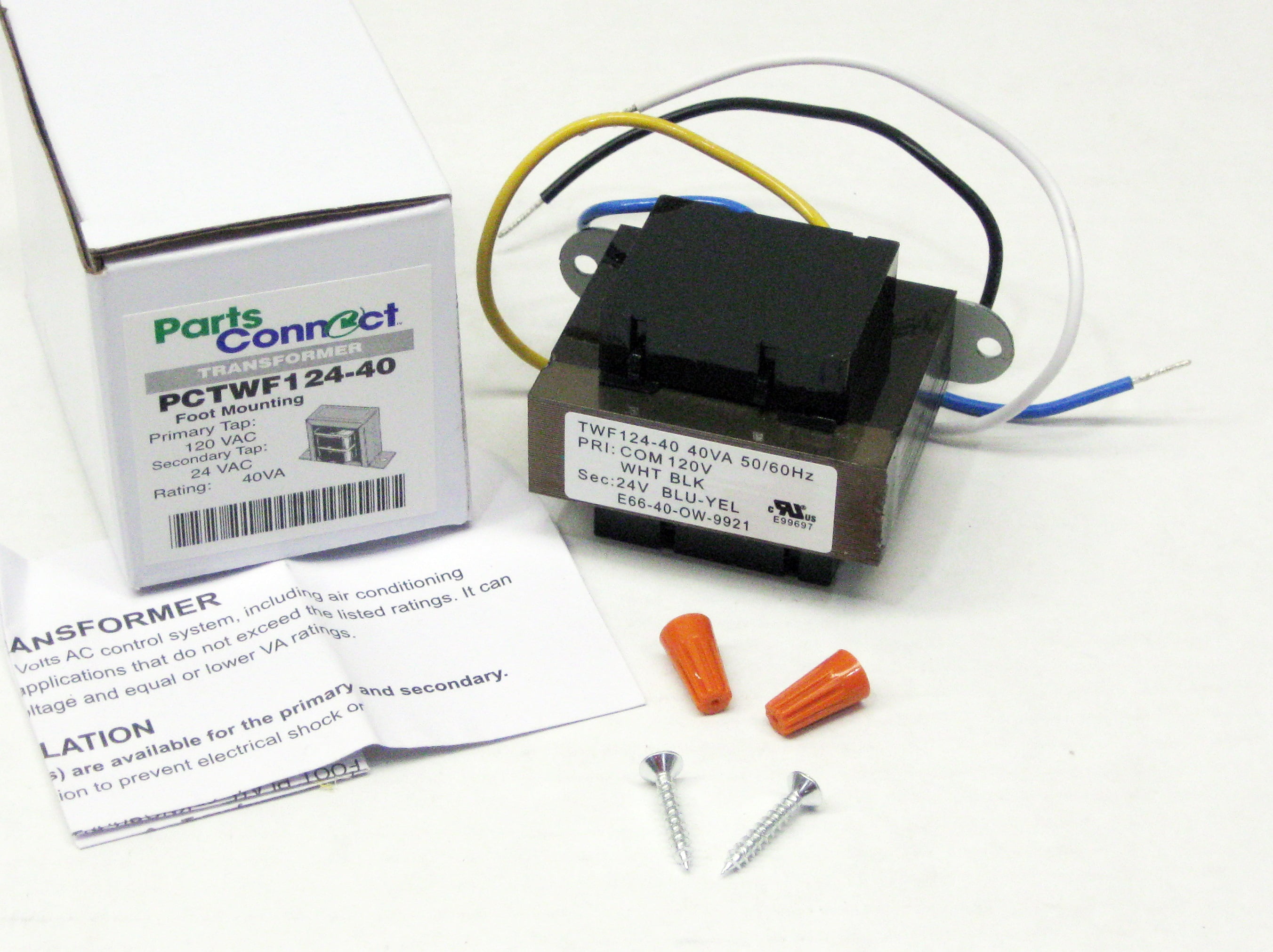
40VA Transformer Primary 120V Volt 24V Secondary HVAC Furnace Foot Mount
How to Wire a 24V Transformer - Hunker Step 1. Inspect the wires connected to the 24 VAC transformer. There are usually four wires--two black and two more that are yellow, green or blue. The two black wires will be connected to the 120 VAC input, while the yellow, green or blue wires are the 24 VAC output.

120V/24V Transformer for Brooders
Practical Machinist - Largest Manufacturing Technology Forum ...

4-1611453-7 - Productsunlimited - Te Connectivity ...

120V/24V Transformer for Brooders | Hog Slat
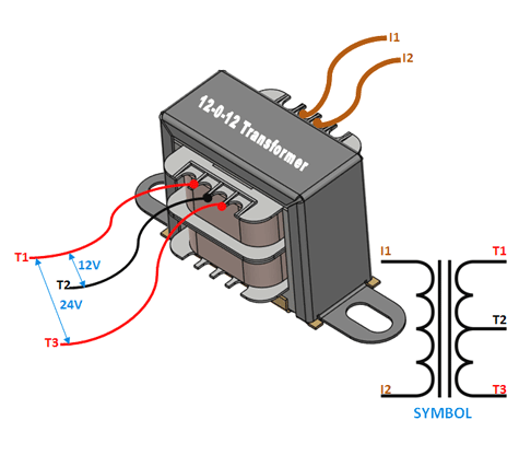
12-0-12 Centre Tapped Transformer: Wiring, Specifications ...
York Luxaire Transformer 110 120 24 volt 025-30889-000

I have a 277v line voltage Thermostat that I need to convert ...
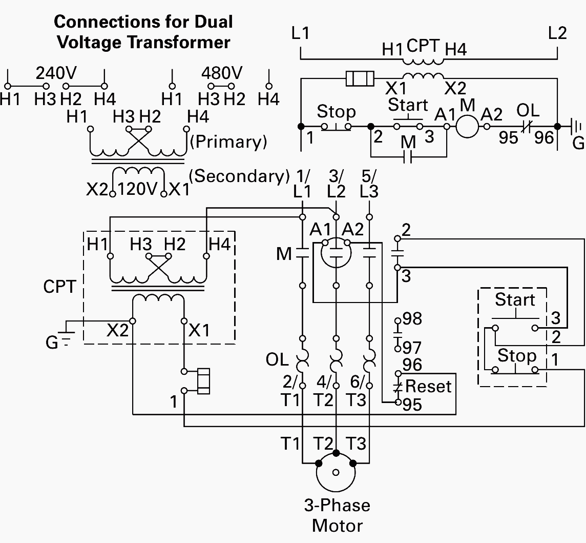
Wiring of control power transformer for motor control ...
Which HVAC 24v Transformer can you use for Replacement on almost Every Unit! Transformers

How to wire a transformer in series or parallel (with animation) | Basic Electronics

Electrical Principles Guide: Single-Phase Transformers
Class II Multi-Mount Transformer Primary 120 Volts Secondary ...

Posts tagged: Workshop - radare.net
How to Wire a Multi-tap Transformer - Functional Devices, Inc.
RCD, ELCI GFI between ABYC and ISO codes | Page 3 | Boat ...
40VA Transformer Primary 120V Volt 24V Secondary HVAC Furnace ...

Square D 9070T100D13 :: Control Transformer, 100VA, 120 -12 ...
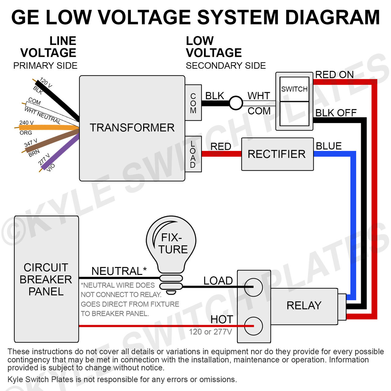
GE Low Voltage Transformer for Older Home Lighting System RT1 RT2
Orion's Photos: portrait - mechanical - illinois_furnace

Electricity 101: Basic Fundamentals | Industrial Controls

Edwards Signaling™ 592 590 Class 2 Signaling Transformer, 120 ...

24 Volt Fan Center for AireShare Fans
Wiring transformer | Terry Love Plumbing Advice & Remodel DIY ...
24 Volt HVAC transformer (120v/208v/240v Inputs & 24VAC-40VA Output)

BOJACK EI Type Isolation Transformers PRI.120/208/240 V AC 50/60Hz 24 V AC 40 VA 4031F Class 2 Control Transformers with Foot Mount Replacement for ...

Transformer with wire leads and quick connect universal 24 ...

Control Circuits for HVAC Systems Quality HVAC Tips 101

Transformers and VA Ratings | York Central Tech Talk
75VA Transformer Primary 120V 208V 240V 480V Volt 24V Secondary HVAC Furnace Multi Tap


Comments
Post a Comment