40 refrigerator pv diagram
PDF Chapter 19. Heat Engines and Refrigerators The area enclosed within a pV curve is A.the work done by the system during one complete cycle. B. the work done on the system during one ... • The gas in a refrigerator can exhaust heat QH to the hot reservoir only if the gas temperature is higher than the hot-reservoir temperature TH. Heat energy is • heat engines and refrigerators using ideal gas as working ... draw pV diagram. • use ideal gas law to know n, p, V, T at one point. • use ideal gas law and equations for specific processes for p, V, T.6 pages
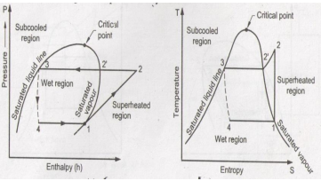
COP Of Air Refrigerator Working On Reversed Carnot Cycle ... Fig (1) and fig (2) shows the p-v and T-s diagram of a refrigeration system working on reversed Carnot cycle. The process involved in reversed Carnot cycles are as follows 1-2. isentropic compression process During this stage, air is compressed isentropically. Pressure and temperature increases, the specific volume of decreases.

Refrigerator pv diagram
Impossible refrigerator (thermodynamics and PV diagrams ... All it says is that we have a rectangular cycle on a PV diagram, and we are trying run it counterclockwise to make a refrigerator (unlike the image where it's running in clockwise direction). Nov 29, 2014 #32 Andrew Mason Science Advisor Homework Helper 7,692 403 Avatrin said: The question doesn't say it is a reversible heat engine. Bell Coleman Cycle with PV and TS diagram - Mechanical Walkins Above figure shows PV and TS diagram of Bell Coleman Cycle .Here P1 , V1 , T1, S1 represents volume, pressure ,temperature and entropy respectively at point 1 and so on. Below is the elaboration of four steps of Bell Coleman Cycle :-. i) 1-2 : Isentropic Compression :-. This is the first step of Bell Coleman Cycle. 2: Schematic pV-diagram for the thermoacoustic cycle (Fig ... Download scientific diagram | 2: Schematic pV-diagram for the thermoacoustic cycle (Fig. (1.4)). a) Refrigerator; the area ABCD represents the work used. b) Prime ...
Refrigerator pv diagram. Thermodynamics eBook: Carnot Refrigerator and Heat Pump The P-v diagram of the reversed Carnot cycle is shown on the left. The Carnot Refrigerator and Heat Pump A refrigerator or a heat pump that operates on the reversed Carnot cycle is called a Carnot refrigerator or a Carnot heat pump. The coefficient of performance (COP) of reversible or irreversible refrigerator or heat pump is given by How a Refrigerator Works - HomeTips For the technically minded, here is how the process works. The cool vapor is moved from the evaporator by the compressor and is then compressed into a high-temperature, high-pressure vapor and pumped into the condenser. In the condenser, the high-temperature, high-pressure gas gives up its heat as cooling air moves through the condenser coils. Stirling Cycle: Efficiency with P-v and T-s Diagram This process is represented by a graph 2-3 on p-v and T-s diagram. In this process, heat is rejected to the regenerator. 3. Process 3-4 (Isothermal expansion) The air is now compressed isothermally, practically, at a constant temperature T3 in the engine cylinder from V3 to V4. This process is represented by the graph 3-4 on p-v and T-s diagrams. Improvement on energy consumption of a refrigerator within ... The main methodology diagram shows a comparison of (a) source type AC/DC supplying Inverter-driven refrigerator; (b) the performance of two types (Inverter-driven/non inverter-driven) of refrigerator. The instantaneous power consumption ( P s) consists of two parts, the refrigerator power consumption ( P r) and power conversion losses ( P c ).
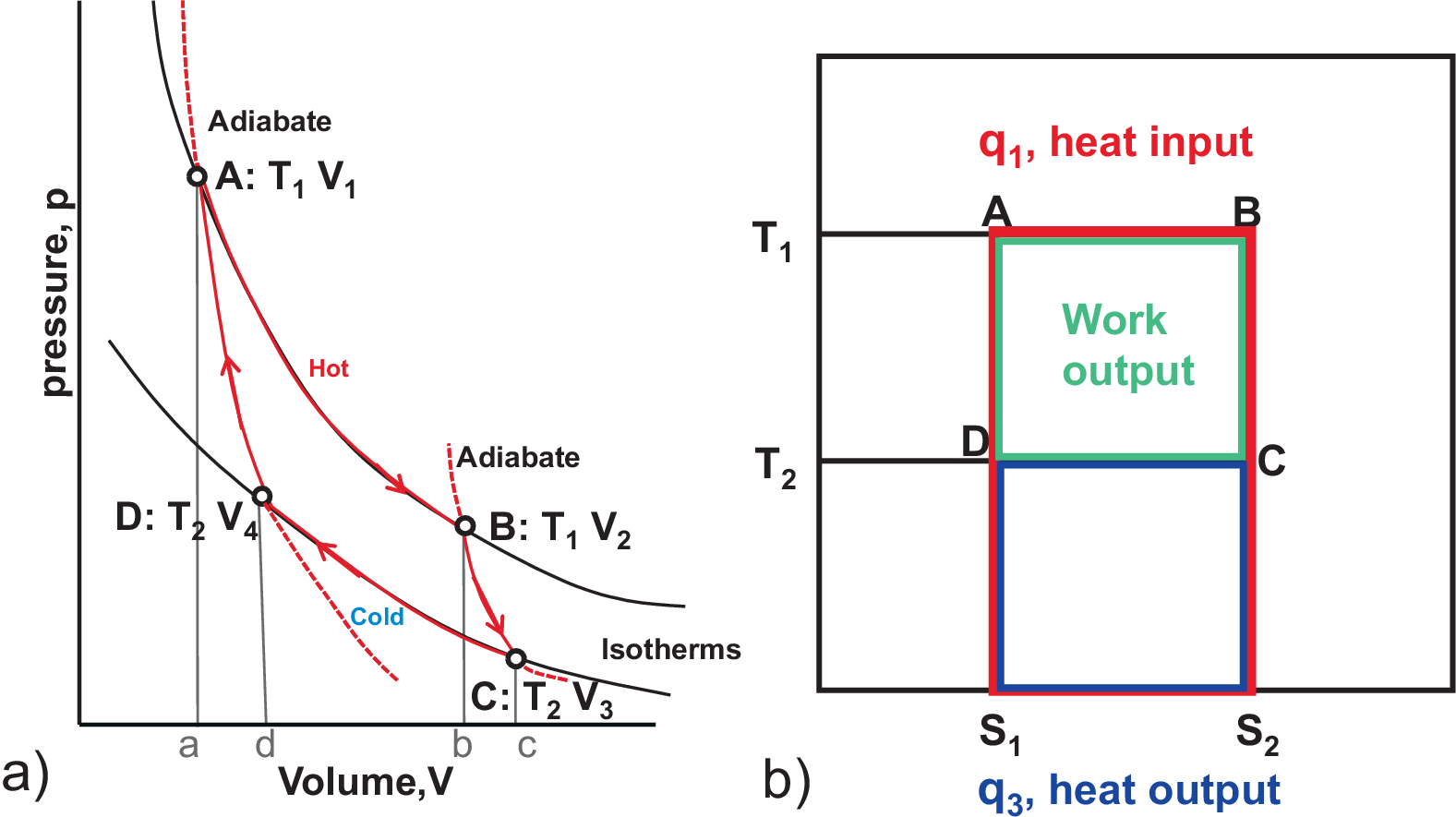
Carnot Vapour compression Refrigeration cycle The COP of the refrigerator, Practical Vapour compression refrigeration cycle (a) schematic diagram (b) T-s diagram . Application of the first law of thermodynamics to the control volume compressor, condenser, throttle and evaporator gives (W s) compressor =h 2-h 1 . Q H =h 2-h 3 . h 3 =h 4 . and Q L =h 1-h 4 . The COP of the refrigerator is ... Thermodynamics - Eastern Illinois University A Carnot cycle can also be represented on a PV diagram. A refrigerator is a heat engine, run in reverse. W + Q c = Q h. Another form of the Second Law of Thermodynamics is that. It is not possible to make a heat engine whose only effect is to absorb heat from a high-temperature region and turn all that heat into work. That is ... Carnot Cycle - pV, Ts diagram | Processes | nuclear-power.com pV diagram of Carnot cycle. The area bounded by the complete cycle path represents the total work done during one cycle. The Carnot cycle is often plotted on a pressure-volume diagram (pV diagram) and a temperature-entropy diagram (Ts diagram).. When plotted on a pressure-volume diagram, the isothermal processes follow the gas's isotherm lines, adiabatic processes move between isotherms, and ... Difference Between a Refrigerator, Heat Pump, and Heat ... A refrigerator works between cold body temperature (T1) and atmospheric temp (Ta) whereas the heat pump operates between hot body temp (T2) and the atmospheric temperature (Ta). A refrigerator used for cooling in summer can be used as a heat pump for heating in the winter season. so Wp = Q2-Q1 (C.O.P)hp = Q2/ WR = Q2 / (Q2-Q1) Where hp-heat pump
Heat Engine - Definition, Heat Engine Efficiency ... - BYJUS Heat Engine PV Diagram. Heat engines can be typically illustrated on a PV diagram, Pressure-Volume (PV) diagrams are the basic tool for the study of heat engines that use gas as the working substance.PV diagram will be a closed-loop for a cyclic heat engine. ... A normal refrigerator is an example of a heat pump and in reverse, it is a heat ... P-V Diagram for a refrigerator - Boston University Physics P-V Diagram for a refrigerator The P-V diagram shown below is over-simplified, showing two adiabatic processes and two isobaric (constant pressure) processes but neglecting the two changes of state that occur. This gives you the general flavor of the cycle, however. DataTableApp loaded Impossible refrigerator (thermodynamics and PV diagrams ... Homework Equations U = 0.5fnRT (U = internal energy, f = degrees of freedom, n = number of moles of gas, R = ideal gas constant, T = temperature) dU = Q + W = TdS - PdV (S = entropy, V = volume, Q = heat, W = work, P = pressure) PV = nRT The Attempt at a Solution What are PV diagrams? (article) - Khan Academy Each point on a PV diagram corresponds to a different state of the gas. The pressure is given on the vertical axis and the volume is given on the horizontal axis, as seen below. Every point on a PV diagram represents a different state for the gas (one for every possible volume and pressure).
Midterm review
The pressure-volume (pV) diagram and how work is produced ... The pressure-volume (pV) diagram is drawn by measuring the pressure inside the cylinder, and plotting its value against the angle of the crankshaft, over a complete engine cycle (720°). Let's see what's happening in the cylinder during each piston stroke, how the pressure and volume are changing inside the cylinder.

Heat Engine Cycle
PDF Refrigeration Cycle - Simon Fraser University refrigerator or heat pump that operates on the reversed Carnot cycle is called a Carnot refrigerator or a Carnot heat pump. Fig. 5-1: T-s diagram and major components for Carnot refrigerator. The reversed Carnot cycle is the most efficient refrigeration cycle operating between two specified temperature levels. It sets the highest theoretical COP.

How does a Refrigeration Cycle work? | What is Refrigeration?
Boston University Physics Applets: P-V Diagram for a ... This web page is an interactive physics simulation on the cycles a refrigerator goes through. The user can see that this cycle requires work to move heat, as compared to an engine moving heat to do work. This is part of a collection of similar simulation-based student activities. Please note that this resource requires Java Applet Plug-in.
Vapor-Compression Refrigeration
File:Refrigeration PV diagram.svg - Wikimedia Commons File:Refrigeration PV diagram.svg. Size of this PNG preview of this SVG file: 512 × 427 pixels. Other resolutions: 288 × 240 pixels | 576 × 480 pixels | 921 × 768 pixels | 1,228 × 1,024 pixels | 2,456 × 2,048 pixels.

REFRIGERATION
Air Refrigerator Working On Bell-Coleman Cycle with PV and ... Fig show P-V and T-S diagram of bell coleman refrigerator. Here P 1, V 1, T 1, S 1 represents the pressure, volume, temperature, entropy of air respectively at point 1. And so on. It represents the corresponding condition of air when it passed through the component. 1-2: Isentropic Compression

Stirling Refrigeration Cycle (a) P-V diagram (b) T-S diagram ...
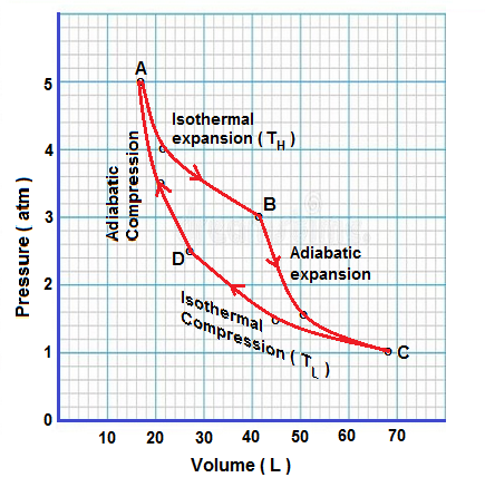
Carnot Cycle -Definition, Theorem, Efficiency, Diagrams ... The heat Q 2 is taken from the sink and external work is done on the working substance and heat Q 2 is rejected to the source at a higher temperature (principle of a refrigerator). Moreover, in the Carnot's heat engine, the process of isothermal and adiabatic expansions and compressions are carried out very-very slowly i.e. quasi-static.
P-V and T-S Diagrams
PDF Quantitative Stirling Cycle Measurements: P-V Diagram and ... As shown in Fig. 2, the pressure sensor was then connected to the syringe tip using tight-fit - Fig. 2. Photograph of the setup to measure the Stirling cycleP-V diagram. A photogate and chopper are used to sense the position of the power piston while a pressure sensor and voltage probe monitor the gas pressure. Fig. 3.

Vapour Compression Refrigeration | Working with pv and Ts diagram | RAC | Sourav Kumar
Solved Consider a refrigerator that uses a Carnot cycle ... Consider a refrigerator that uses a Carnot cycle based on an ideal gas to remove heat from a cold reservoir at T c and reject heat into a hot reservoir at T h. (a) Draw a PV diagram for the Carnot refrigerator, with pressure on the vertical axis, and volume horizontally.

Air Refrigerator Working On Bell-Coleman Cycle with PV and TS ...
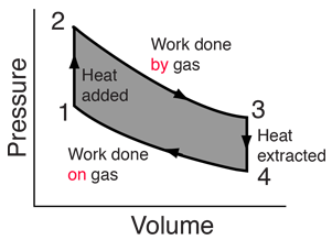
Solved 21-6 CHAPTER 21 Heat Engines and Refrigerators 21.4 ... The figure shows the pV diagram of a refrigerator Adiabats Stage B During which stages is heat added to the gas? During which is heat removed from the gas? During which stages is work done on the gas? During which is work done by the gas? Circle the answers that complete the sentence: The temperature of the hot reservoir must be i. > the ...

Bell Coleman Cycle with PV and TS diagram - Mechanical Walkins
Refrigerators - The Physics Hypertextbook indicator diagram vapor compression refrigeration In 1834 an American inventor named Jacob Perkins obtained the first patent for a vapor-compression refrigeration system, it used ether in a vapor compression cycle. Joule-Thomson (Kelvin) expansion Low pressure (1.5 atm) low temperature (-10 to +15 °C) inside

Refrigeration Cycle P-V Diagram - GATE Solution Academy ...
Refrigerators & PV Diagrams - Physics Video | Clutch Prep Video explaining Refrigerators & PV Diagrams for Physics. This is one of many videos provided by Clutch Prep to prepare you to succeed in your college classes.
Heat Engines
2: Schematic pV-diagram for the thermoacoustic cycle (Fig ... Download scientific diagram | 2: Schematic pV-diagram for the thermoacoustic cycle (Fig. (1.4)). a) Refrigerator; the area ABCD represents the work used. b) Prime ...
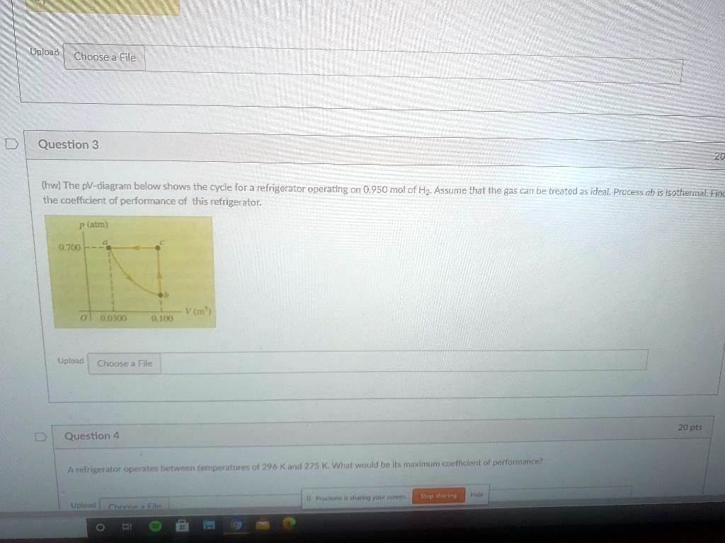
SOLVED:Upload Choose File Question 3 (hw} The pV-diagram ...
Bell Coleman Cycle with PV and TS diagram - Mechanical Walkins Above figure shows PV and TS diagram of Bell Coleman Cycle .Here P1 , V1 , T1, S1 represents volume, pressure ,temperature and entropy respectively at point 1 and so on. Below is the elaboration of four steps of Bell Coleman Cycle :-. i) 1-2 : Isentropic Compression :-. This is the first step of Bell Coleman Cycle.

REFRIGERATION
Impossible refrigerator (thermodynamics and PV diagrams ... All it says is that we have a rectangular cycle on a PV diagram, and we are trying run it counterclockwise to make a refrigerator (unlike the image where it's running in clockwise direction). Nov 29, 2014 #32 Andrew Mason Science Advisor Homework Helper 7,692 403 Avatrin said: The question doesn't say it is a reversible heat engine.
![Solved]: Can someone please help with all parts of this que](https://media.cheggcdn.com/media/ce3/ce30d94e-39f0-4e09-8e8b-43b60ebc1cb0/phpGOaEpn)
Solved]: Can someone please help with all parts of this que

Carnot Refrigeration Cycle, Refrigeration Cycle, Assignment Help

Solved - The pV-diagram in Fig. P20.51 Answer | Course Eagle
Carnot cycle: p-V diagram and T-S diagram
Solved Refer to the PV diagram below showing the | Chegg.com

Bell Coleman Cycle with PV and TS diagram - Mechanical Walkins

Solved The Stirling cycle, represented on the PV diagram ...
Refrigeration & Liquefaction
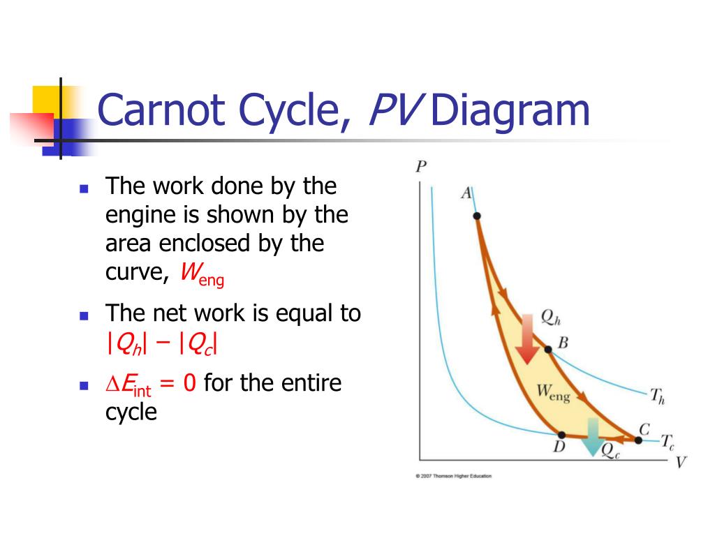
PPT - Carnot Cycle, PV Diagram PowerPoint Presentation, free ...
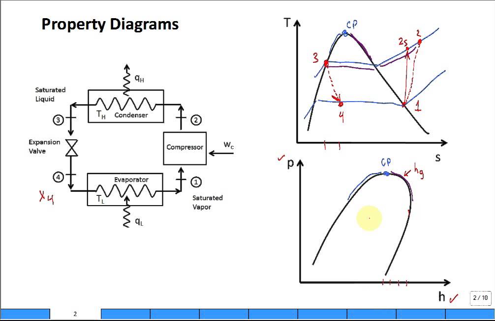
Property diagrams TS and PH for refrigeration

Carnot heat pump (or Carnot refrigerator)

Refrigeration Cycle: A Helpful Illustrated Guide - refconhvac.com
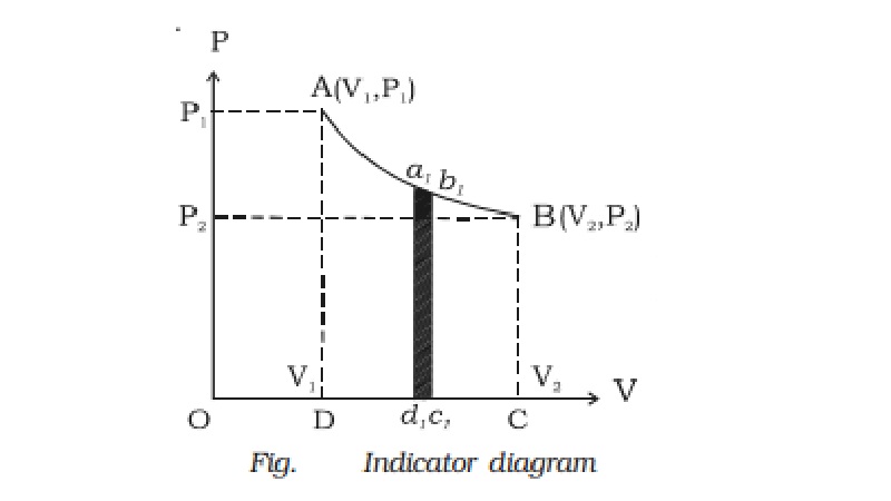
Indicator diagram (P-V diagram)
show four steps of carnot engine in p v graph write the ...
heat engines and refrigerators using ideal gas as working ...

COP Of Air Refrigerator Working On Reversed Carnot Cycle with ...
Carnot Cycle (& Otto Cycle) | Physics Forums
Heat engines and the second law
Isothermal process on p-V, T-V, and p

Chapter 3a - The First Law - Closed Systems - Energy (updated ...

Complete Carnot Cycle, efficiency, PV diagram, TS diagram ...
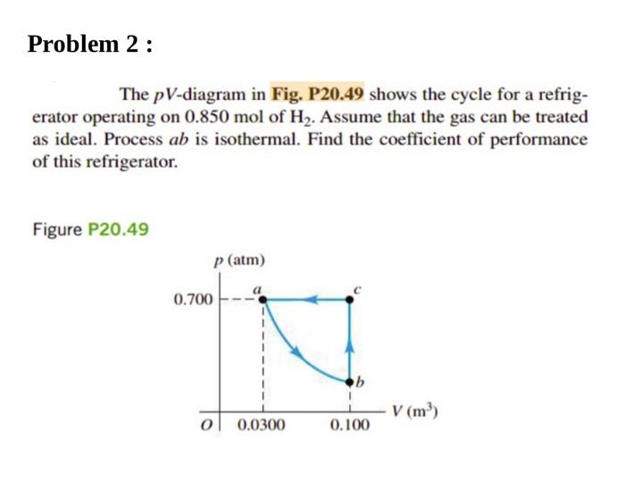
Solved Problem 2: The pV-diagram in Fig. P20.49 shows the ...
Explain vapour compression refrigeration cycle on T-S and p-h ...

Refrigeration Cycles - Mech Engineering: Thermodynamics - UCL ...
chapter 6
JSRAE, Japanese Society for Refrigerating and AirConditioning ...


Comments
Post a Comment