41 draw the shear diagram for the beam. mastering engineering
The Ultimate Guide to Shear and Moment Diagrams - DegreeTutors.com Mastering Shear Force and Bending Moment Diagrams Your complete roadmap to mastering these essential structural analysis skills. After completing this course… You will be fully competent in drawing shear force and bending moment diagrams for statically determinate beams and frames. 6-9 Rules of Shear Force Diagram (Part 2) - Internal Force Diagrams | Coursera Video created by Universidade de Ciência e Tecnologia de Hong Kong for the course "Mastering Statics". We will get to the most important part, which is analyzing frames and beams to calculate their internal forces and to draw axial, shear and ...
Solved 7.88 Draw the shear and moment diagrams for the beam. | Chegg.com Best Answer. This is the best answer based on feedback and ratings. Transcribed image text: 7.88 Draw the shear and moment diagrams for the beam. Previous question Next question.

Draw the shear diagram for the beam. mastering engineering
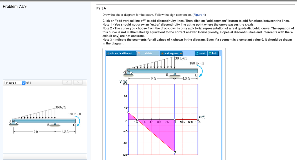
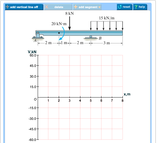
Solved Draw the shear diagram for the beam. Follow the sign | Chegg.com Civil Engineering questions and answers. Draw the shear diagram for the beam. Follow the sign convention. (Figure 1) Click on "add vertical line off" to add discontinuity lines. Then click on "add segment" button to add functions between the lines. Note 1 - You should not draw an "extra" discontinuity line at the point where the curve passes ... Mastering Engineering Graphical Answer Type Video Transcript - Pearson In this tutorial, students will practice their problem solving skills by drawing shear and bending moment diagrams from the free-body diagram of a beam. Let me show you how students add answers to this type of question and how the system responds with feedback. Place vertical lines at 0, 4, 16, and 20 meters. Solved Draw the shear and moment diagram of the | Chegg.com Engineering; Civil Engineering; Civil Engineering questions and answers; Draw the shear and moment diagram of the indeterminate beam. USE THREE-MOMENT EQUATION. Final answer must be boxe rounded off to the nearest 3 decimal places. Please show COMPLETE solution; Question: Draw the shear and moment diagram of the indeterminate beam. USE THREE ...
Draw the shear diagram for the beam. mastering engineering. Answered: Draw the shear and moment diagram of… | bartleby Q: Draw the shear and moment diagram and determine the Vmax and Mmax of the overhanging beam shown…. A: Click to see the answer. question_answer. Q: Determine the x- and y-coordinates of the centroid of the shaded area. Input values in two (2)…. Solved problem 7.80 part A draw the shear diagram for the - Chegg problem 7.80. part A. draw the shear diagram for the beam. part B. draw the moment diagram for the beam. Expert Answer. Who are the experts? Experts are tested by Chegg as specialists in their subject area. We review their content and use your feedback to keep the quality high. Pearson Education, Mastering Engineering | Pearson Graphical Answer Type problems enable students to practice their problem-solving skills by drawing shear and bending moment diagrams from the free-body diagram of a beam in Mastering Engineering. The Vector Drawing Tool in Mastering Engineering helps students learn how to visualize answers just like they were working a problem out by hand. (Solved) - Draw the shear diagram for the beam. Follow the sign convention ... Draw the shear diagram for the beam. Follow the sign convention. (Figure 1) Click on "add vertical line off" to add discontinuity lines. Then click on "add segment" button to add functions between the lines. Note - The curve you choose from the drop-down is only a pictorial representation of a real quadratic/cubic curve.
6-10 Rules of Shear Force Diagram (Part 3) - Internal Force Diagrams - Coursera We will get to the most important part, which is analyzing frames and beams to calculate their internal forces and to draw axial, shear and moment diagrams. Contrary to most textbook presentations, we will adopt a notation that is universally adopted by engineers when using moment diagrams. 6-8 Rules of Shear Force Diagram (Part 1) 2:15 Drawing Shear and Moment Diagrams Example- Mechanics of Materials and ... - YouTube this is a detailed example of shear and moment diagrams, i recommend skipping around to the sections shown below if you already have a feel for the subject:i... Shear Force and bending moment diagram - ExtruDesign Steps to draw Shear force and Bending moment diagrams. In SFD and BMD diagrams Shear force or Bending moment represents the ordinates, and the Length of the beam represents the abscissa. Consider the left or the right portion of the section. Add the forces (including reactions) normal to the beam on the one of the portion. SHEAR FORCES AND BENDING MOMENTS | DegreeTutors.com Determining shear and moment diagrams is an essential skill for any engineer. Unfortunately it's probably the one structural analysis skill most students struggle with most. So in this post we'll give you a thorough introduction to shear forces, bending moments and how to draw shear and moment diagrams.
Answered: Draw the shear and moment diagram of… | bartleby Engineering Mechanical Engineering Q&A Library Draw the shear and moment diagram of the given beam. Consider support A is roller and B is pin. 4 kN 2 kN 2 kN/m B 1 m 3 m 1 m Consider support A is roller and B is pin. 4 kN 2 kN 2 kN/m B 1 m 3 m 1 m Solved 7-51. Draw the shear and moment diagrams for the | Chegg.com Organize/present your graphs following these instructions: a. First, provide a diagram of the entire beam, showing all relevant geometry, loading, and show the support reactions b. Directly below the beam diagram, provide the internal shear (V) diagram. C. Directly below the shear diagram, provide the internal moment (M) diagram. d. 6-7 Introduction to Axial, Shear and Bending Moment Diagram - Internal Force ... We will get to the most important part, which is analyzing frames and beams to calculate their internal forces and to draw axial, shear and moment diagrams. Contrary to most textbook presentations, we will adopt a notation that is universally adopted by engineers when using moment diagrams. 6-6 Sign convention: A critical review 7:18. How to Draw Shear Diagrams | ReviewCivilPE This is the first point of data, draw a line from zero to negative 10. Continuing on the next force is 21.67 lb upward at the A support. Extend the line horizontally until it is at A and then add the 21.67 force to it. The shear diagram is now at 11.67 lb on the positive side. The next force is -10 lb.
Part D Knowing how a positive internal bending moment affects ...
Job leading course on Drafting and Design Using Revit | Skill-Lync : Skill-Lync The above methods will be used to determine bending moment and shear force diagrams of a single span statically indeterminate beam Analysis of propped cantilever beam subjected to uniform load and concentrated load Week 04 - Introduction to internal hinges in beams and two span continuous beams In this session, you will learn
Solved Draw the shear diagram for the beam. Follow the sign ...
Job leading course on Drafting and Design Using Revit | Skill-Lync : Skill-Lync Analyze the beam & draw bending moment and shear force diagrams In this project, the students need to determine the loading on the beam of a building whose data will be given, analyze the beams, and draw bending moment and shear force diagrams. Modeling of four-storied three-bay frames using ETABS
Multimedia Tutorials For Drawing Shear Force And Bending ...
Mastering Shear Force & Bending Moment Diagrams - DegreeTutors.com You will be fully competent in drawing shear force and bending moment diagrams for statically determinate beams and frames. You will understand the relationship between external loading and the shear forces and bending moments they induce. You will understand the link between internal stresses and their shear force and bending moment resultants.

Draw the shear and moment diagrams for the cantilevered beam
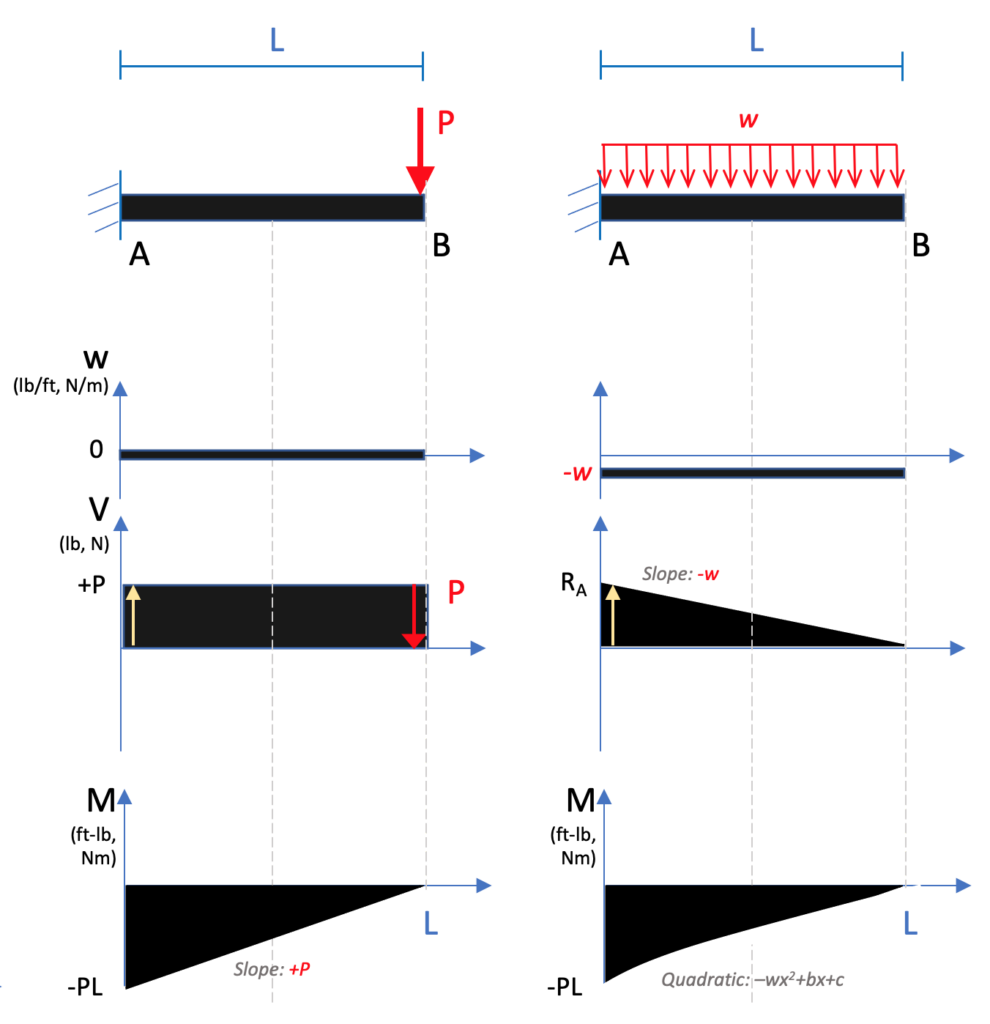
PDF Statics - TAM 210 & TAM 211 Mastering Engineering Tutorial 8 ... Draw the shear and bending moment diagrams for the beam. Note that since the applied load is a single distributed load along the entire length of the beam, then V(x) and M(x) are continuous functions. We will see that V(x) and M(x) will be
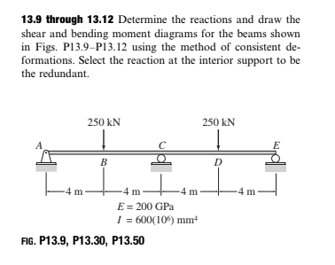
Answered: 13.9 through 13.12 Determine the… | bartleby
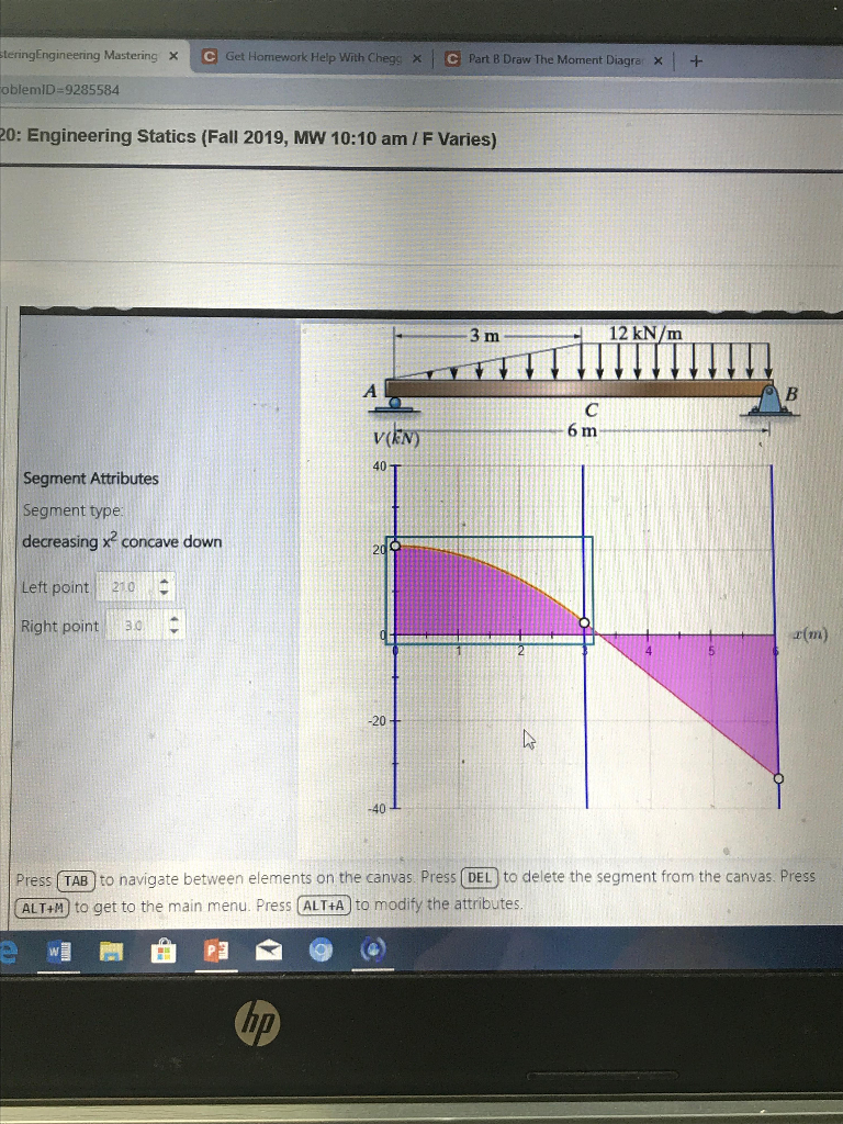
Answered: Draw the shear diagram for the beam.… | bartleby Engineering Mechanical Engineering Q&A Library Draw the shear diagram for the beam. Follow the sign convention. (Figure 1) Click on "add vertical line off" to add discontinuity lines. Then click on "add segment" button to add functions between the lines.
6.2 Shear/Moment Diagrams – Engineering Mechanics: Statics
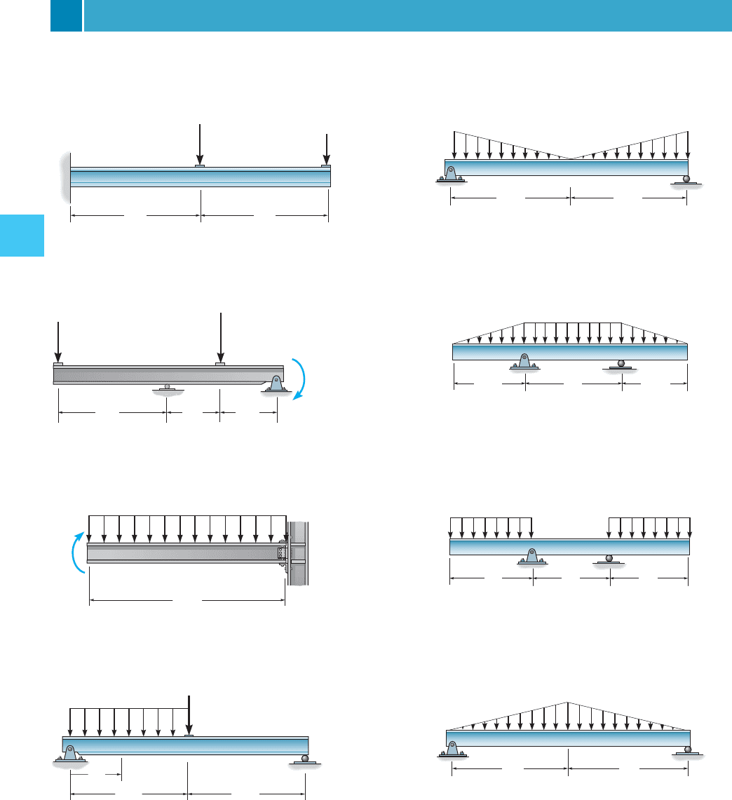
Shear Load and Bending Moment Diagrams First draw the free-body-diagram of the beam with sufficient room under it for the shear and moment diagrams (if needed, solve for support reactions first). 2. Draw the shear diagram under the free-body-diagram. The distributed load is the slope of the shear diagram and each point load represents a jump in the shear diagram.
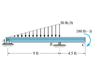
Solved Problem 7.59 Part A Draw the shear diagram for the ...
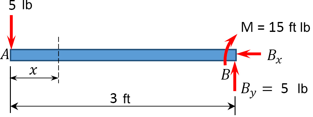
Draw the shear and moment diagrams for the beam, and determine the shear and ... Mechanics of Materials - Instructor Solutions Manual [EXP-4667] Draw the shear and moment diagrams for the beam, and determine the shear and moment throughout the beam as functions of x. Step-by-Step Report Solution Verified Solution Scan the QR Code To Continue Browsing on Your mobile Device.
Hibbeler R.C. Structural Analysis
Mastering Shear Force and Bending Moment Diagrams - Udemy You will be fully competent in drawing shear force and bending moment diagrams for statically determinate beams and frames. You will understand the relationship between external loading and the shear forces and bending moments they induce. You will understand the link between internal stresses and their shear force and bending moment resultants.

Features for Students | Mastering Engineering | Pearson
Answered: Draw the shear diagram for the beam.… | bartleby Draw the shear diagram for the beam. Follow the sign convention. (Figure 1) Click on "add vertical line off" to add discontinuity lines. Then click on "add segment" button to add functions between the lines. Note 1- You should not draw an "extra" discontinuity line at the point where the curve passes the x-axis.
Solved] Draw the shear force bending moment diagrams of the ...
Calculate and draw the transverse shear stress | Chegg.com Calculate and draw the transverse shear stress diagram of the beam. Show transcribed image text. Expert Answer. Who are the experts? Experts are tested by Chegg as specialists in their subject area. We review their content and use your feedback to keep the quality high. Transcribed image text: 1000 kgf 800 kg 2 m 600 kgf/m 8 m 2 m 2 m 15 cm Sol ...

Solved) - Draw the shear and bending moment diagrams for the ...
Mastering Shear Force and Bending Moment Diagrams [9.6/10] How much does the Mastering Shear Force and Bending Moment Diagrams course cost? Is it worth it? The course costs $21.99. And currently there is a 82% discount on the original price of the course, which was $119.99. So you save $98 if you enroll the course now. The average price is $17.4 of 111 Civil Engineering courses on Udemy.

Statics 7.82 - Draw the shear and moment diagrams for the beam.
Solved Draw the shear and moment diagram of the | Chegg.com Engineering; Civil Engineering; Civil Engineering questions and answers; Draw the shear and moment diagram of the indeterminate beam. USE THREE-MOMENT EQUATION. Final answer must be boxe rounded off to the nearest 3 decimal places. Please show COMPLETE solution; Question: Draw the shear and moment diagram of the indeterminate beam. USE THREE ...
Solved part a Draw the shear diagram for the beam. part b ...
Mastering Engineering Graphical Answer Type Video Transcript - Pearson In this tutorial, students will practice their problem solving skills by drawing shear and bending moment diagrams from the free-body diagram of a beam. Let me show you how students add answers to this type of question and how the system responds with feedback. Place vertical lines at 0, 4, 16, and 20 meters.

Understanding Sign Conventions in Structural Analysis ...
Solved Draw the shear diagram for the beam. Follow the sign | Chegg.com Civil Engineering questions and answers. Draw the shear diagram for the beam. Follow the sign convention. (Figure 1) Click on "add vertical line off" to add discontinuity lines. Then click on "add segment" button to add functions between the lines. Note 1 - You should not draw an "extra" discontinuity line at the point where the curve passes ...
Solved: Statics Question: draw V and M DiagramsPart ADraw

Solved) - Consider the compound beam shown in (Figure 1 ...

Ultimate Guide to Shear Force and Bending Moment Diagrams ...

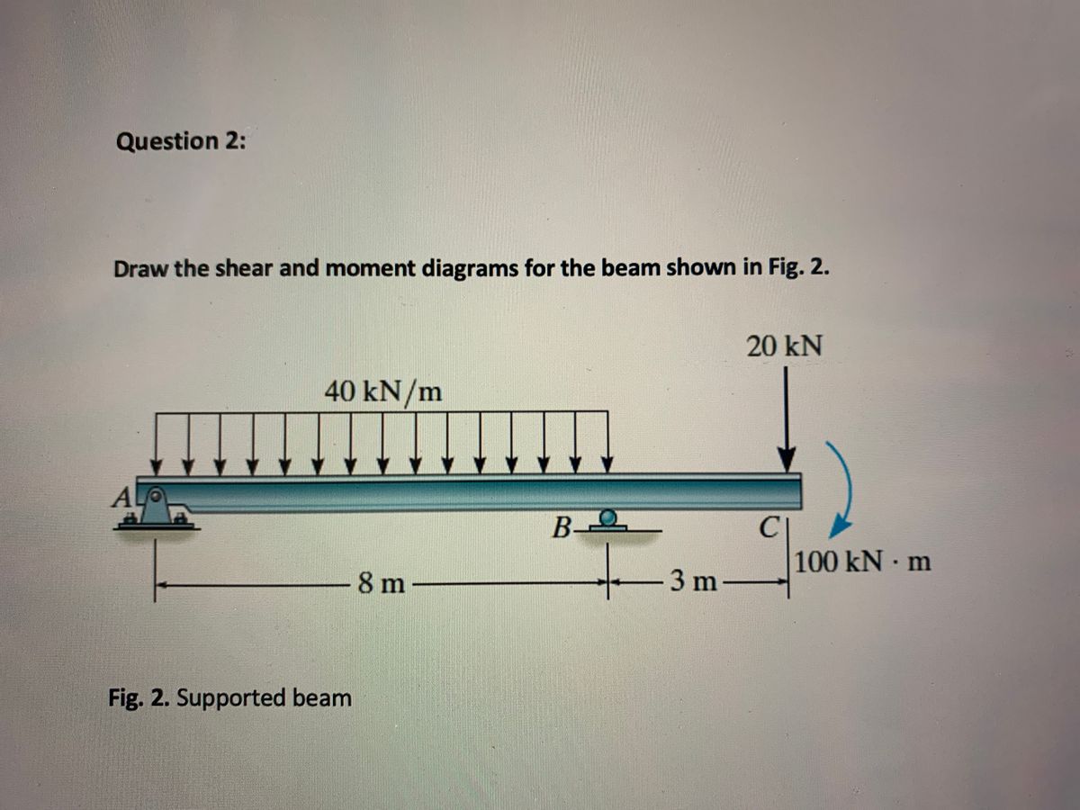
Draw the shear and moment diagrams for the beam shown in Fig ...

hw 7 sou.pdf - HWK #7: Due 7/24/19 at 9:00 am CDT 1 of 14 ...
Solved Draw the shear diagram for the beam. Draw the moment ...
6.2 Shear/Moment Diagrams – Engineering Mechanics: Statics

Solved) - *7-56, Draw the shear and moment diagrams for the ...

Statics 7.71 - Draw the shear and moment diagram for the beam ...

Hibbeler, Modified Mastering Engineering with Pearson eText ...

Solved) - Problem 7.85 Part A Draw the shear diagram for the ...
Features for Students | Mastering Engineering | Pearson

Features for Educators | Mastering Engineering | Pearson

Part D Knowing how a positive internal bending moment affects ...
Answered: Draw the shear and moment diagrams for… | bartleby
Solved Shear and Bending Moment Diagrams Learning Goal ...
The Ultimate Guide to Shear and Moment Diagrams ...

Statics 7.82 - Draw the shear and moment diagrams for the ...

6-15 Example 2: Bending Moment Diagram - Internal Force ...
The Ultimate Guide to Shear and Moment Diagrams ...
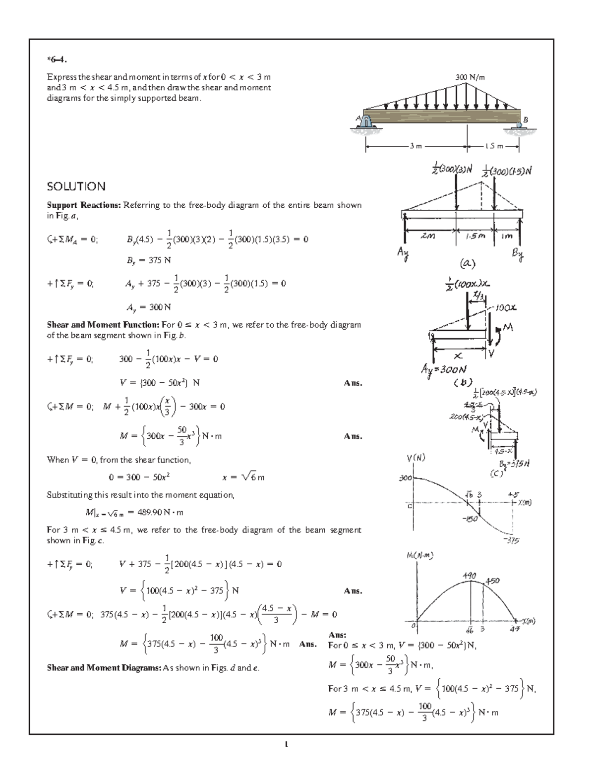
Assignment Solutions-Set 01 - *6–4. Express the shear and ...
Solved problem 7.80 part A draw the shear diagram for the ...

Features for Students | Mastering Engineering | Pearson
Hibbeler R.C. Structural Analysis
Solved] 4.1 only please | Course Hero
Solved) - Draw the shear force and bending moment diagrams ...
Solved Problem 7.90 Part A Draw the shear diagram for the ...


Comments
Post a Comment