39 air ride wiring diagram
The 4-level air suspension system in the allroad quattro is a logical development of the self-levelling system in the Audi A6. The principles of the suspension/air suspension system and the description of those system components which are identical in the 4-level air suspension system are described in SSP 242. Basic pressure switch triggered wiring for your air suspension compressors. Relay wiring diagram, for air compressor circuits.
There is a lot involved in is air ride suspension system ! A 60a Fuse in the under hood fuse block Marked VSES / ECAS .This is the power for the compressor . There is a air suspension control module , Ride height switch , Fuse in the I / P fuse block 4 WD 15a supply's B+ to ride height switch .

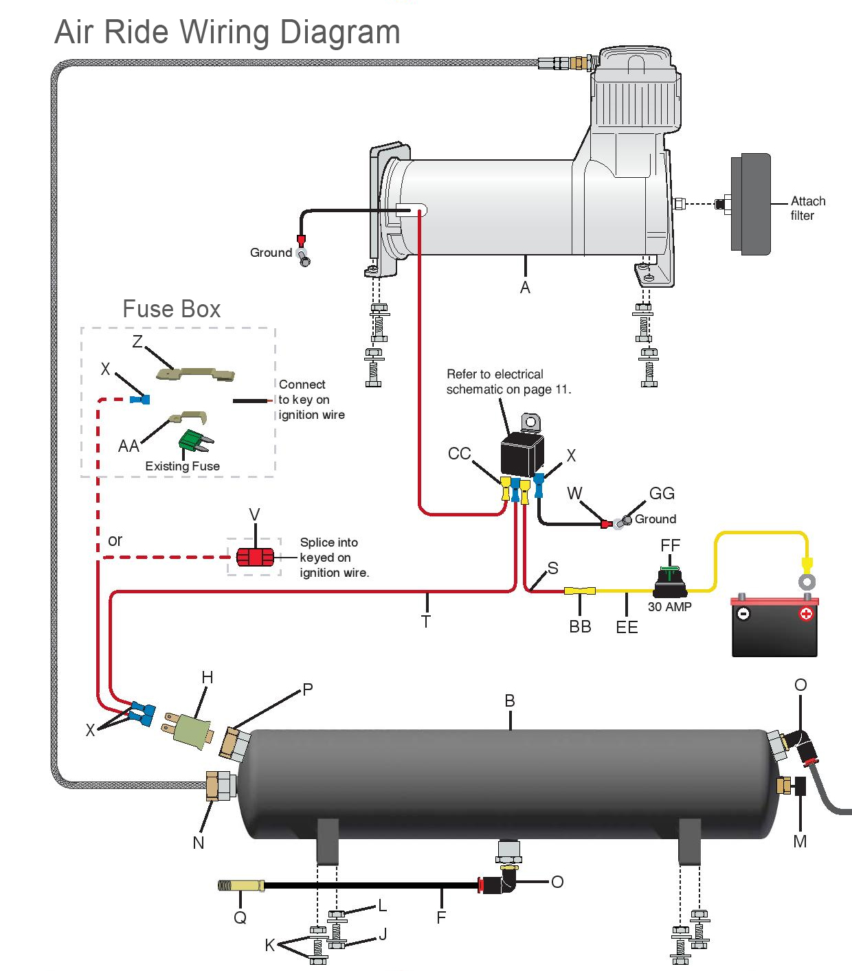
Air ride wiring diagram
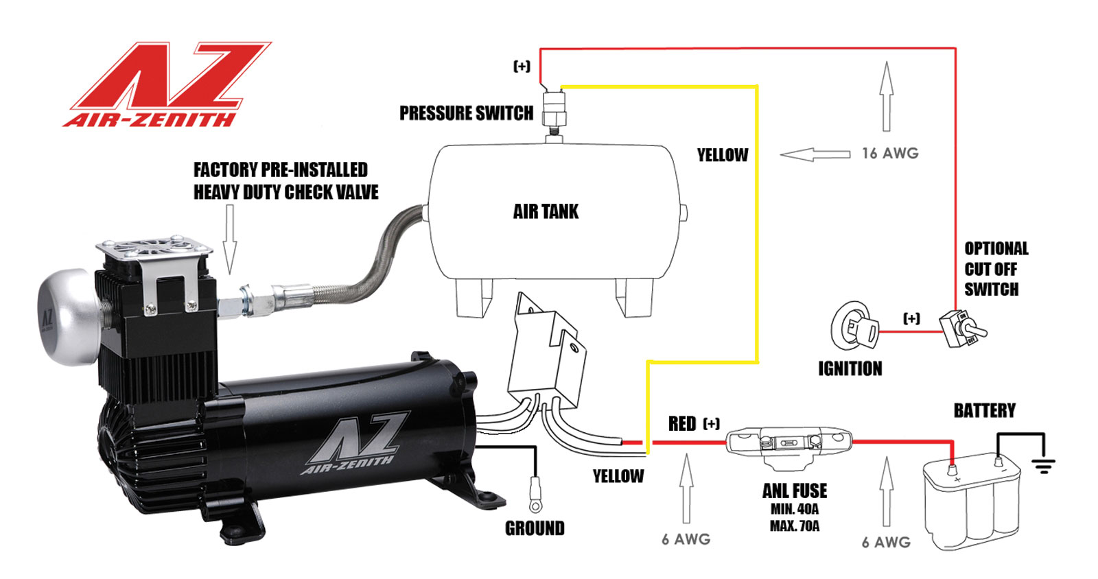
Wiring Diagrams & schematics July 19, 2014, 12:53:33 pm. Yahoo Message Number: 96466 I have tried to get the wiring schematics from CC for my 2007 Inspire 360 with C9 Caterpillar to no avail. They say they don't have them. If anyone has this same coach I would gladly pay to have you reproduce the above and mail them to me. Air Ride; Hijacker Hydraulics; CCE Hydraulics; Wire Wheels; Diagrams; Videos; Contact Us; Returns & Refunds; Search for: Home / Diagrams. Diagrams onething 2020-02-25T19:50:15-05:00. AIR RIDE DIAGRAMS. HYDRAULICS DIAGRAMS. Search products. Product categories. Online Specials (22) New Products (37) CCE APPAREL (14) Hijacker Hydraulics (266) Air ... Air ride suspension wiring diagram. If you need further help you can find more info below. Ez air ride dual 444c wiring diagram to tank 12v 40a relay do not use red wire to tank 12v 40a relay do not use red wire pressure switch to keyed power source either prong fuse battery relays relays help to increase the life expectancy of pressure ...
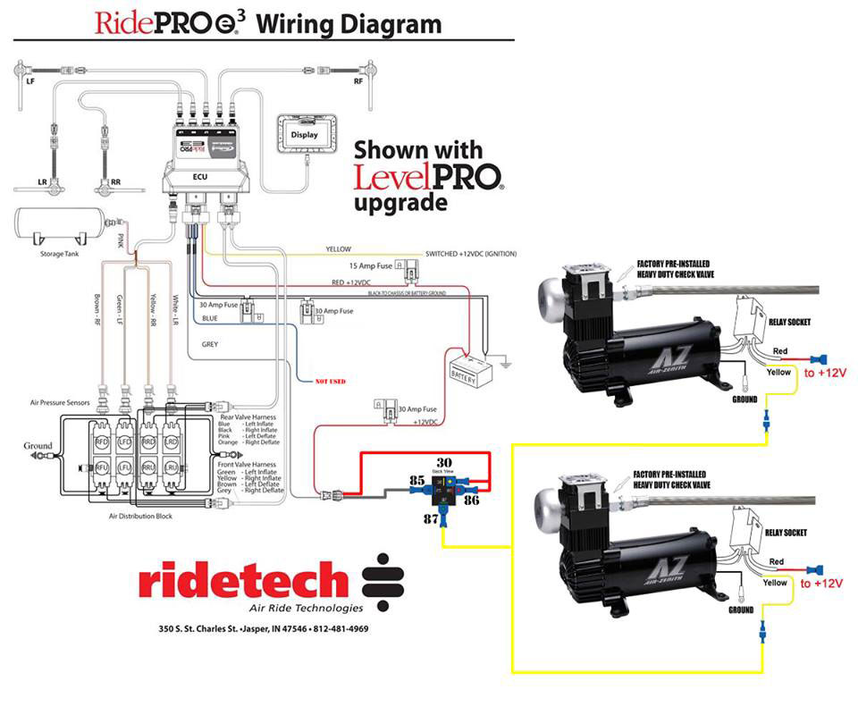
Air ride wiring diagram. Mounting the Air Tank • The air tank can be mounted anywhere on the vehicle in any position, So long as the sensor is not pointed down. • There is an 1/8" port in the tank that will accept the tank pressure sensor. Mounting the RidePro Air Valves • The valves, like the compressor, are sealed and can be mounted in the same locations. Air adjustable shock absorber is a conventional shock enclosed in an air chamber that extends when air pressure in chamber increases. Air Drier Air drier, attached to compressor outlet, absorbs moisture from air being delivered to air adjustable shock absorbers. Air drier contains a valve that maintains a minimum air pressure of 7-14 psi (. 49 ... 77 Awesome Air Ride Relay Wiring Diagram. 77 Awesome Air Ride Relay Wiring Diagram- A manage relay is used in the automotive industry to restrict and amend the flow of electricity to various electrical parts inside the automobile. They allow a small circuit to govern a future flow circuit using an electromagnet to govern the flow of electricity ... Air Ride Suspension Wiring Diagram - One of the most hard automotive fix tasks that a mechanic or fix shop can take is the wiring, or rewiring of a car's electrical system.The misery in point of fact is that every car is different. later than exasperating to remove, replace or fix the wiring in an automobile, having an accurate and detailed Air Ride Suspension Wiring Diagram is vital to ...
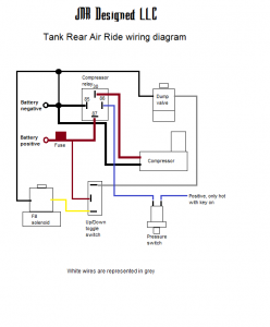
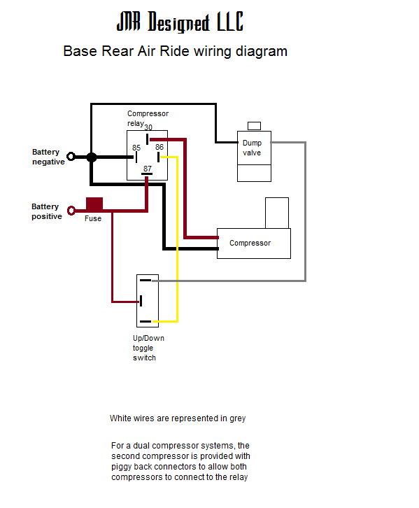
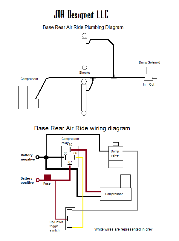
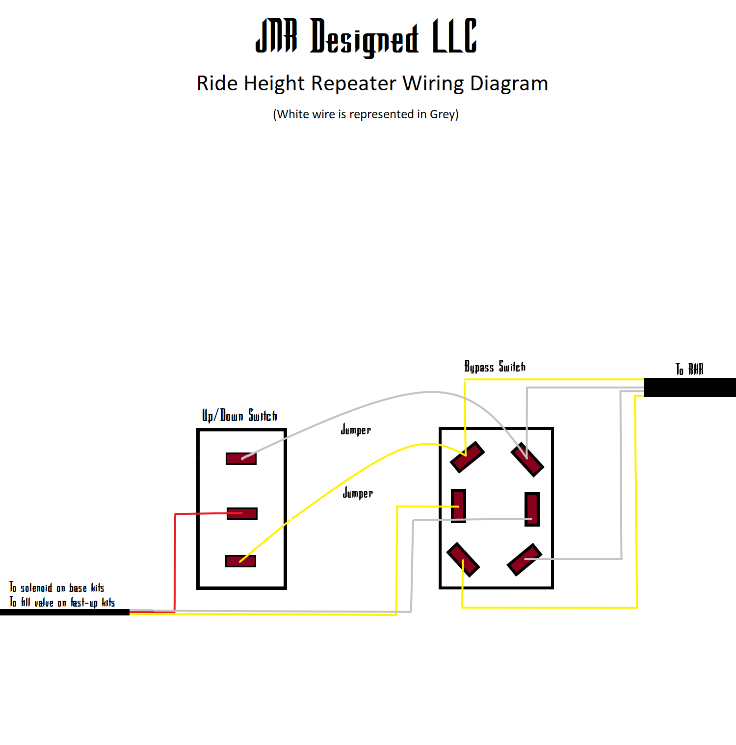
SOURCE: 2004 yukon xl denali self-leveling rear air shocks. There's a lever that connects the driver-side rear shock to the Automatic Level Control module (the air compressor and the ride-height sensor). Disconnect the lever from the shock and rotate it up and hold it. The compressor should kick in when you hold in place after a few seconds. Air Ride Suspension Wiring Diagram - wiring diagram is a simplified up to standard pictorial representation of an electrical circuit.It shows the components of the circuit as simplified shapes, and the aptitude and signal friends in the company of the devices. Wiring Diagram For Air Ride On Motorcycle With A Tank. Print the wiring diagram off plus use highlighters to trace the signal. When you make use of your finger or perhaps the actual circuit with your eyes, it is easy to mistrace the circuit. 1 trick that We 2 to printing a similar wiring plan off twice. Dirty Air Usa Basic Rear Suspension System. Air It Out Legend Suspension Install Hot Bike. Stage 1 Kit. Base Rear Air Ride Harley Touring Model Non Year Specific Jnr Designed. Man Tg A Wiring Diagram. Air Suspension Inoperative Check These First Rustyautos Com. 2 Way Toggle Switch Harness 73 Legend Air Suspensions.
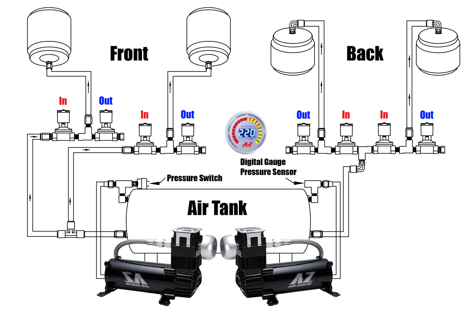
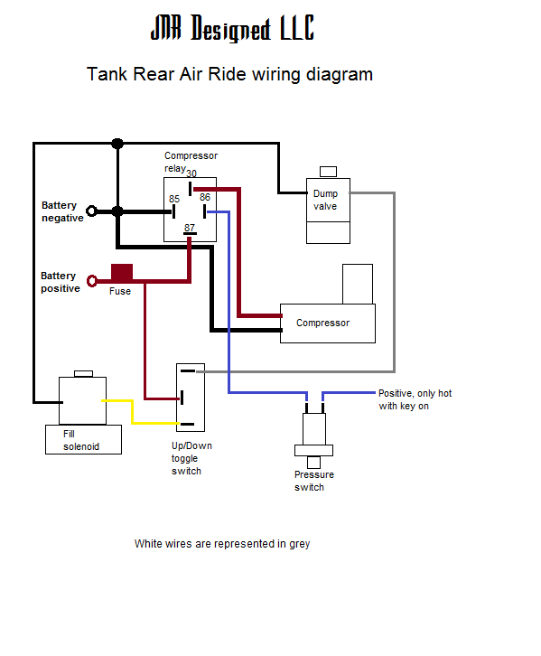
1 Installation Guide & Operation Manual RideTech 350 S. St. Charles St. •Jasper, IN 47546 • 812-481-4969 TM Front and Rear Air Ride ... Download Here Link to Download Wiring Diagrams:Download Here Link to Download Tank Wiring and Pneumatic Diagrams:Download Here Standard Install with Toggle Switch: _____Standard Install with Handlebar Switch: _____ Standard Inst ... Bmw 5 Series X5 Car Wiring Diagram Png 960x1242px Air Suspension Area Auto Part. Tech support air zenith schematic diagram of electronically wiring diagrams car suspension compressor installation instructions tank rear jnr designed manual ride management kit inoperative check pressure switch land rover range sport hi lo rod s v2k drifter automotive electronic porsche cayenne navistar bmw 5 ... Air Ride Valve Wiring Diagram - wiring diagram is a simplified standard pictorial representation of an electrical circuit. It shows the components of the circuit as simplified shapes, and the talent and signal associates in the company of the devices. A wiring diagram usually gives assistance very nearly the relative viewpoint and pact of ...
Air Ride solenoid Wiring Diagram- wiring diagram is a simplified conventional pictorial representation of an electrical circuit.It shows the components of the circuit as simplified shapes, and the knack and signal friends surrounded by the devices.
Power and Height sensor wiring . Power Supply . As shown in the diagram, the system power is supplied with a fuse holder, 60 Amp fuse, and wires designed to be routed directly to the battery. Sensor Wiring . The sensor wires are labeled for driver side and curb side angle sensors. The driver FRONT wires are
Electronic Suspension Land Rover Range Rover Sport Le 2008 System Wiring Diagrams Wiring Diagrams For Cars
Air Ride Wiring Diagram. Air Ride Wiring Diagram from jleiwig.20megsfree.com. Print the wiring diagram off and use highlighters in order to trace the signal. When you employ your finger or stick to the circuit together with your eyes, it's easy to mistrace the circuit. 1 trick that I 2 to printing the same wiring plan off twice.
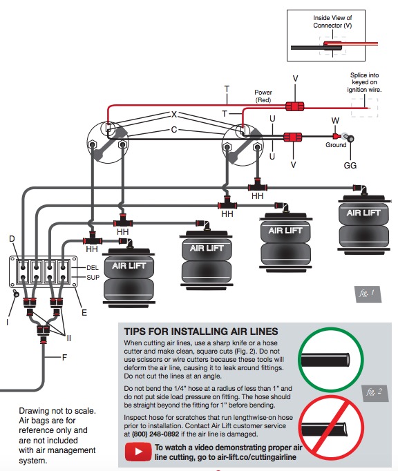
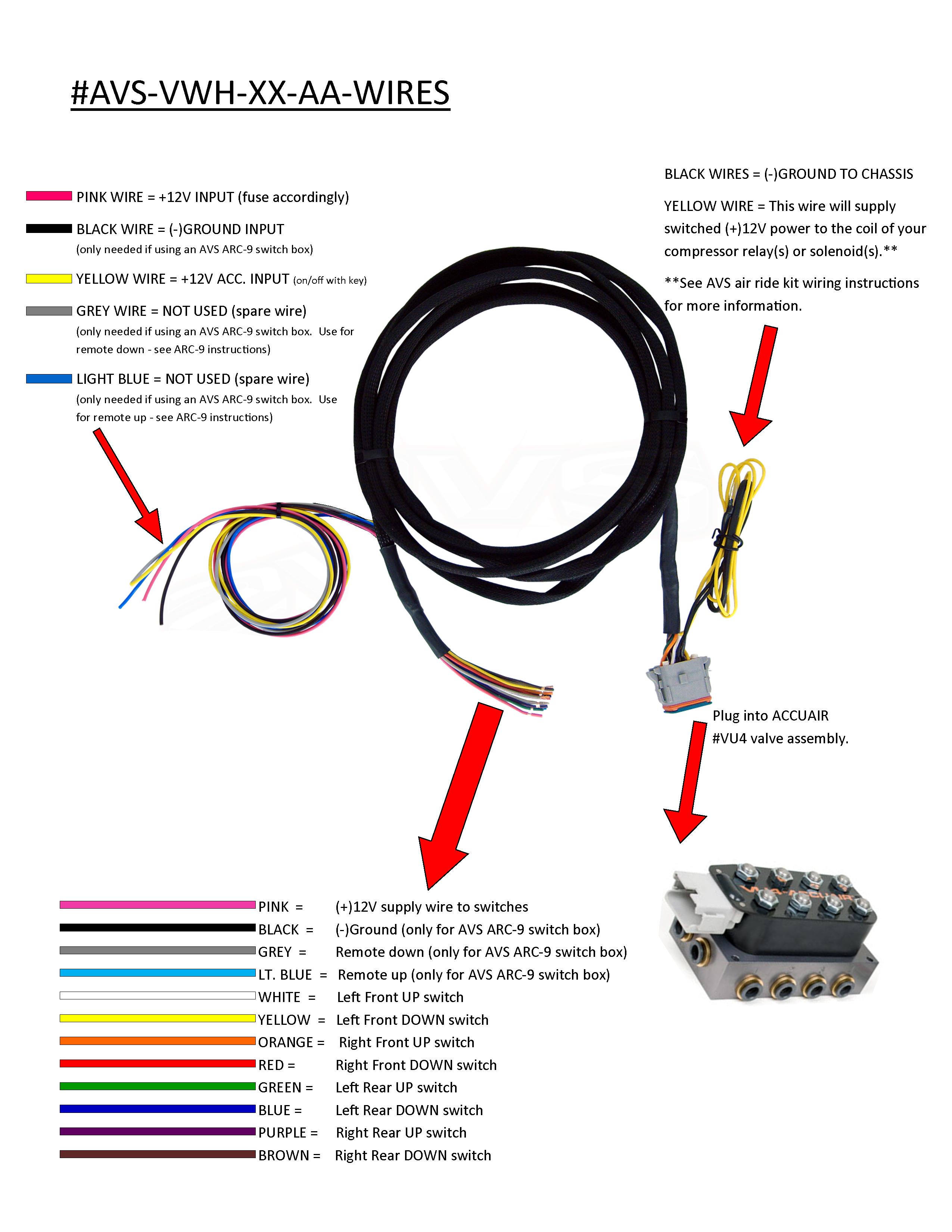
Air Ride Manual 4-Valve Management System Wiring Diagram for most Manual Operated Air Ride Systems. These wiring diagrams cover all "C" Model Viair Compressors as Included with our Manual Air Ride Management Kits . Use the Following Diagram for Twin Compressor Setups . We recommend all items are installed by a qualified individual(s).
1 WIR8000 Air valve wiring harness ... • Plumbing & Wiring Diagram page 3 ... • The ride height sensors have a 180-degree range of movement, but only a 90-degree range of "electrical authority". This means that they will only read through the middle 90
Here are a couple examples on how to do this... First, most tanks we use have 1/2" ports on them. That port will flow a lot of air. You can put two viair compressors on one port. A 480 only puts out about 1/2 a cfm at high pressure. 1/2 + 1/2 = 1. A 1/2" port will easily flow more than 1 cfm.
i. Connect each wire to its corresponding valve as shown on the Non-PnP Wiring Schematic. ii. If you have purchased this Smart-Ride controller with one of Airbagit.com's Air Engine valve assemblies, or Air Force then the Valve Loom will plug right into the Air Engine's white 9 pin plug. See Air Engine Wiring Schematic.
77 Awesome Air Ride Relay Wiring Diagram- A manage relay is used in the automotive industry to restrict and amend the flow of electricity to various electrical parts inside the automobile. They allow a small circuit to govern a future flow circuit using an electromagnet to govern the flow of electricity inside the circuit.
Here you will find installation, plumbing and wiring instructions for all of our EZ Air Ride kits. If you need further help, you can find more info below. "Do it once, do it right! Don't do it again." ™. (916) 337-2231. info@ezairride.com.
Click here for a wiring diagram. Click here for a plumbing diagram. Click here for plumbing diagram when tank and air ride are ordered as a combo. FITMENT. All Harley Touring Models when twin saddle bag guards are not used (not available for the 97/98 compressors)
Diagram Based Air Ride Technologies Wiring. Tech Support Air Zenith. Airrx Air Kit Rx User Manual Users Spal Usa. 20 Unique Motorcycle Air Ride Diagram. Tech Support Air Zenith. Tech Support Air Zenith. Part 30154000 4000 Series Ridepro 4 Way Compressor System 3 Manualzz.
Air ride suspension wiring diagram. If you need further help you can find more info below. Ez air ride dual 444c wiring diagram to tank 12v 40a relay do not use red wire to tank 12v 40a relay do not use red wire pressure switch to keyed power source either prong fuse battery relays relays help to increase the life expectancy of pressure ...
Air Ride; Hijacker Hydraulics; CCE Hydraulics; Wire Wheels; Diagrams; Videos; Contact Us; Returns & Refunds; Search for: Home / Diagrams. Diagrams onething 2020-02-25T19:50:15-05:00. AIR RIDE DIAGRAMS. HYDRAULICS DIAGRAMS. Search products. Product categories. Online Specials (22) New Products (37) CCE APPAREL (14) Hijacker Hydraulics (266) Air ...
Wiring Diagrams & schematics July 19, 2014, 12:53:33 pm. Yahoo Message Number: 96466 I have tried to get the wiring schematics from CC for my 2007 Inspire 360 with C9 Caterpillar to no avail. They say they don't have them. If anyone has this same coach I would gladly pay to have you reproduce the above and mail them to me.

Trust The Air Suspension Ride Pros Find Exclusive Deals On Hot Rod Suspension Lift Kits Lowering Kits Lambo Doors Air Springs Air Bags Billet Wheel Adapters Towing Kits Air Shocks Air Suspension









Comments
Post a Comment