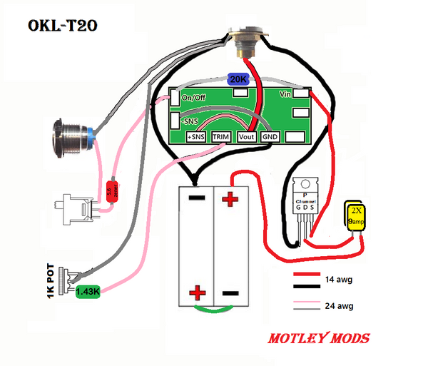
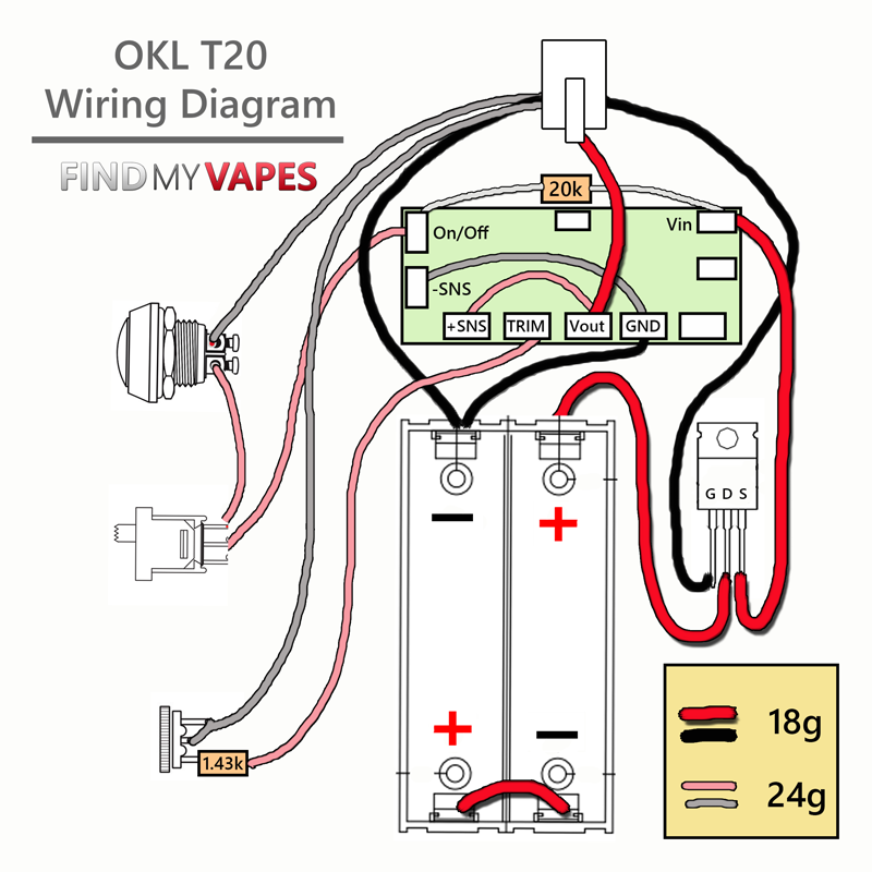
40 diy box mod wiring diagram
Feb 01, 2010 · The immobilizer system in those models is composed of (1) the engine ECM, (2) the immobilizer ECU, (3) the ring antenna with the amplifier in the ignition lock, (4) the keys and wiring. So if the problem persists, I would first check the wiring. I am not sure if you have the wiring diagram of that model, but if not, I am including it here. 24.07.2021 · I followed your diagram to a tee, with the exception of using rubber propane hoses with 3/8 female flare ends. I felt better about its flexibility than the danger of bending copper lines accidentally over time… I’m a little (a lot) heavy handed. Otherwise, your directions are killer. I built the locker with the vent the same way and it works perfectly!
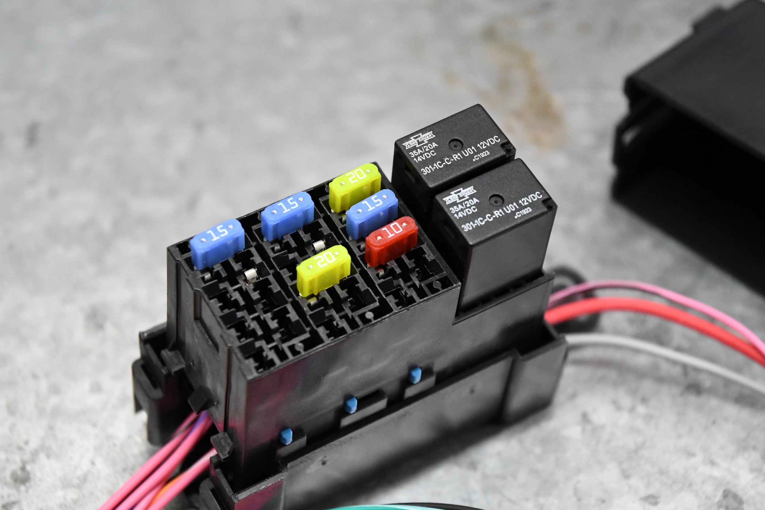
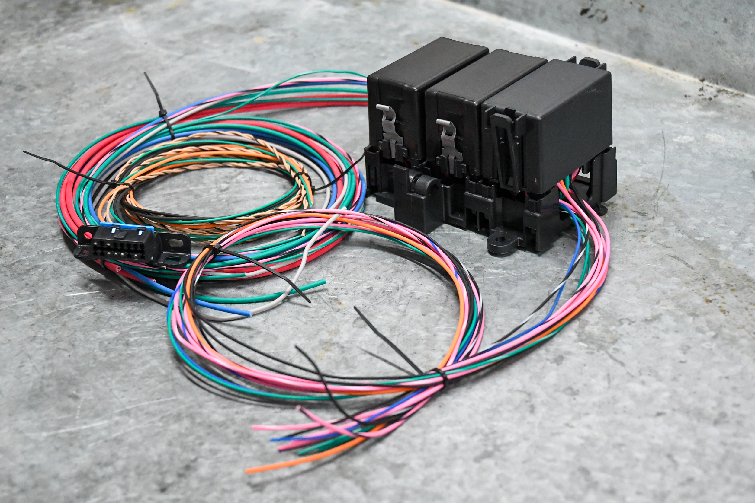
13.08.2019 · Below is a wiring diagram for front, side and rear lights, powered by the six-fuse auxiliary fuse block I installed so that I could feed other accessories and provide more amps for my work lights. The two side lights are wired in parallel with the front light bar so they are turned on with the same switch. In the basic work light setup, the work light connection went to my switch box, which is ...

Diy box mod wiring diagram
Note: each wiring diagram is shown with a treble bleed modification (a 220kΩ resistor in parallel with a 470pF cap) added to the volume pots. ES-335 Prewired Standard Assembly P-GMOD-6. Connect your neck pickup to the pigtail labeled "N" and your bridge pickup to the pigtail labeled "B". Solder your pickup leads to the pigtails after ... Get all of Hollywood.com's best Movies lists, news, and more. 12.06.2018 · How To & DIY; On/Off Switch & LED Rocker Switch Wiring Diagrams. Posted on June 12, 2018 June 12, 2020 by Oznium-dv. Category: Installation Guides, News. 36 comments. How to wire a rocker switch to a circuit is a common query many people have. There is the basic on/off rocker switch that we’re are all familiar with but not everybody knows how to wire, and then there’s also the lighted ...
Diy box mod wiring diagram. 31.01.2014 · A wiring diagram, a voltmeter and a methodical approach are needed to identify what is preventing power from arriving at the heating element. Start at the terminal board where the cord attaches to the dryer. You should have 220 volts between the two outside posts and 110 volts between the center post and either outside post. Then travel down the wiring diagram from one of the outside posts to ... Sep 20, 2013 · Toytec Aluma Series 2.0 (2.5" x 3.5" lift), JBA UCA, Deaver stage 3 Leaf pack, CMC, Viair OBA set-up, KBVOODOO mid rack, Roofnest Condor RTT, CaliRaised Premium Roof Rack w/ 360 lighting, Custom Bed box w/ camp stove built in 17.11.2021 · I downloaded the wiring diagram for what I think was my Tundra 2013 Crewmax. I an trying to identify the connector I have attached to this post. I cannot seem to find it on the wiring schematics. I can't understand why but I will say that the connector is white with 11 pins but only 6 wires connected to it. I am trying to hook up my reverse trigger for backup camera and also the parking brake ... ML triton wiring diagram anyone? by BruceandBobbi. 2 weeks ago. Sub-Forums: Triton News (9/30 ) Challenger. Covering all models. Topics: 3,136 Posts: 47,786 Last Post: Challenger PA 2002 wont go in 4L. 3,136: 47,786: Challenger PA 2002 wont go in 4L. by marshy66. 3 days ago. Sub-Forums: Challenger News (10/52) PB -PC Challenger 2009 - 2014 (2,776/45,848) PA Challenger 1998 - 2006 (345/1,856 ...
Dec 28, 2007 · Gen2 DIY's and guides: DIY: Wiring after-market lights - Tacoma World Forums DIY: OEM Cruise Control - Toyota Forums :: Toyota Nation OEM Intermitted Wipers DIY - Toyota Forums :: Toyota Nation 2005 Tacoma-Writeup on door panel removal - CustomTacos.com Forum Installing AAL's by Chris4x4 Wire Diagram for Anytime Foglight mod by Crom Very happy with result, and has been great for the first couple days using it on a DIY go kart I've been building. Addendum: After figuring out the wiring I ran across the above picture of a similar product. Surprisingly, it appears to be the correct wiring diagram - correct number of wires, correct wire color, but use at your own risk. Before getting into the design of DIY reverb pedal circuit, lets see the concept of reverberation first. Real reverberation happens in a performance chamber when the walls and every object inside reflects the sound back and forth. As the sound bounces back and forth in three dimensional space, the reflections creates more and more complex pattern. The natural process shown in the Figure 1 is ... Meet my CRISS CP/M: the modern single-board 8-bit full-featured DIY personal computer! Amazing functionality: it is not a toy, it is REAL Computer, spy-free Computer and the sophisticated control platform for your projects! Features: OS: CP/M 2.2 = programming languages, text processors, games, business software, ... Instructions: Z80 (Zilog), extended with MUL, DIV, and floating-point, 1us LD ...
12.06.2018 · How To & DIY; On/Off Switch & LED Rocker Switch Wiring Diagrams. Posted on June 12, 2018 June 12, 2020 by Oznium-dv. Category: Installation Guides, News. 36 comments. How to wire a rocker switch to a circuit is a common query many people have. There is the basic on/off rocker switch that we’re are all familiar with but not everybody knows how to wire, and then there’s also the lighted ... Get all of Hollywood.com's best Movies lists, news, and more. Note: each wiring diagram is shown with a treble bleed modification (a 220kΩ resistor in parallel with a 470pF cap) added to the volume pots. ES-335 Prewired Standard Assembly P-GMOD-6. Connect your neck pickup to the pigtail labeled "N" and your bridge pickup to the pigtail labeled "B". Solder your pickup leads to the pigtails after ...











Comments
Post a Comment