40 soldering iron wiring diagram
Read, understand and follow wiring diagrams and work instructions to build cable assemblies and circuit card assemblies. Clean work pieces using chemical solution, file, and wire brush; Skills: soldering, IPC-A-610, J-Standard, J-std, assembly, mill-spec, IPC, lead-free solder, SMT, thru-hole, wave solder, pick and place, Jabil, HDA, PCB To make the wiring connection stable and firm we recommend using Soldering Iron to solder wires and limit switchs pin together and then use Heat Shrink Tube to make it safe. Working with an LED and a Push Button Arduino Project Hub from make wiring diagram arduino sourceDevelop your Arduino code in the cloud and build smart IoT.
TL;DR at the end. Some years ago I needed a particular sort of sensor for my biology research. It was neither high-precision nor particularly complex, but it was strange. No one sold anything like it. So I designed and built the sensors I needed on a minimal budget, on a scratched-up table at home, using a soldering iron half my own age. And then, through a series of improbable events, this sensor got a lot of attention. It made the college I work at look good and to this day if you search for ...

Soldering iron wiring diagram
Hi there, I have a Strandberg Bodin Standard Trem. It's HSS and the pickups (white) I'm putting in are Bridge: D Activator X Middle: Cruiser Bridge Neck: Chopper I'm going to use a 1meg volume push pull pot and a 500k shadow kill pot for the tone control. Dimarzio 5 way super switch Here is where I ask about the theory on the wiring on the guitar and it's positions. 1. Bridge in Series 2. Bridge + Middle in Parallel 3. Middle (Parallel then push pull for out of phase switchi... If you choose this option please note: You will need intermediate soldering techniques and tools to complete DIY ESP Shield along with a Soldering Iron, Solder Sucker, Solder wick. This is not an easy task, and I found I made multiple wiring mistakes before getting it right. Soldering Iron The Soldering Iron is a hand tool that is used in soldering for electronic parts. ... film resistance technology or wire-wound technology. … Read More. AUDIO AMPLIFIER. 4440 IC Amplifier Circuit Diagram | LA4440 IC Datasheet Pdf Download, 4440 ICBoard Price ... 220v to 12v DC Converter Circuit Diagram; SCR Applications | What ...
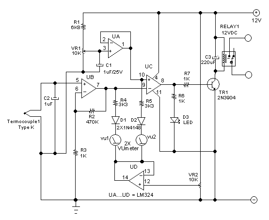
Soldering iron wiring diagram. Feb 27, 2021 · In this post I want to talk about the Arduino Nano: pinout, wiring diagram and programming. What is an Arduino Nano? Arduino Nano is the smallest, typical microcontroller board based on ATmega328P microcontroller made by Atmel. Furthermore your link is for the Tacoma which I haven't heard of this issue on with flipped polarity. So all that being said I would play it safe on your end and make sure you have some wire cutters/strippers, wire sleeves, crimper and/or soldering iron ready to go. Sent from my SM-N986U1 using Tapatalk When I was a kid I got a cheap used EXB404 and played it for a couple years. A buddy borrowed it for a bit and when I got it back it didn’t play. It collected dust in the basement for some time as I’d began to focus more heavily on guitar. For the life of me, I can’t find a wiring diagram for this bass anywhere, I found a few dead links but that’s all. I just cracked it open after a couple years because I have some skills with a soldering iron now, but I’m just completely lost since I opened it... Circuit diagram of soldering iron temperature controller. A soldering station with an adjustable temp control set it to 400 c 752 f. Plumbing as mentioned fitting small pipes together can easily be done with the help of a soldering iron especially if theyre in tight spaces such as a bathroom.
During soldering they may burn away due to overheating. Therefore while soldering a PCB, following precautions should be kept in mind: Erase out the layer of insulation if any, from the PCB. For the wiring, use a soldering ¡ron of lower wattage. For PCB soldering do not use an iron of more than 35 W. Wiring Diagram. LM35 with arduino. So we should connect the VCC to 5V, GND to GND, and the output to the analog pin of Arduino, in this example I put it on A0. ... Now to make sure the sensor is working, I will put a hot soldering iron on the sensor, and we can see the temperature is increasing fast. LM35 with arduino and LCD. Now if I take ... Jan 27, 2021 · Soldering Your Terminals. This section has three steps in the case of the potentiometer connection: 1. First, you should attach a ground wire to the base section from the first terminal on the left. Then, join a little length of wire by covering the exposed section with the soldering flux and iron. Cleanliness is key when soldering. It's good practice to clean the iron. Simply heat the iron and wipe it on a damp piece of tissue paper and you should see the tip of the iron become shiny again with a good coat of solder on it. If this doesn't work, try letting it cool down and clean it with a piece of wet and dry paper.
I would sincerely appreciate it if you can help. I drive a Toyota Camry xle 2003. She’s been tireless (pun intended) and has got me all across the US. Wanted to replace the audio system as she still was running on cassette tapes and the cassette adapter to an Apple phone kept breaking. I got a Boss Audio Systems BVCP9685A. Found the right mount and frame and fits like a glove on the dashboard. Problem is I have no idea how to connect the car’s wiring to the new audio system. I can’t find the rig... Apply for a Harsco Rail Electrical Assembler - 2nd Shift job in West Columbia, SC. Apply online instantly. View this and more full-time & part-time jobs in West Columbia, SC on Snagajob. Posting id: 678172790. My first mechanical keyboard, and my first time picking up a soldering iron. And I decided to build a dactyl manuform. After 3 weekends, 4 pro micros, one trrs socket and many pulled out hairs I finally got it working. All the build guides show you the happy paths, I can’t find many pointing out potholes. So I thought I write up some of the problems and tricks learned. Hoping new comers don’t have to suffer through what I had. First step first, you probably need to buy more than 2 pro micros ... Link to Imgur folder of some pictures of the construction of the cable and an example video of what the picture looks like. http://imgur.com/a/En4rUpD So, the basic jist of things is that I bought this cheap composite + S-video cable some years ago, but now that I have a soldering iron and some time, I wanted to fiddle around with this stuff. I took a segment off from another good quality 5m interconnect S-video cable, but because I didn't have any throwaway RCA cables to sacrifice for the soun...
I need to replace my soldering iron, but once I do, I think that volume pot is coming out to be replaced with a proper one. Thankfully, the wiring diagram for this was easy to find. TedEH , Nov 13, 2021
Oct 13, 2006 · Mercedes Wiring Diagrams, Technical Schematics, Tips & Tricks Hi Guys, I thought I would start ANOTHER THREAD! ;) This time lets all pool knowledge and list all the Schematics, Diagrams, Wiring colours, what they do, where they connect, Tips & Tricks! I do hope this will be another useful...
Hey guys, I am doing my first custom install this week...as soon as I get my parts from TCSS and my chassis' from Etsy haha. I am so excited to be making ground on my custom dual saber/saberstaff combo with a Quick Release from Saberforge. I took apart a LGT core with a Stunt Board and tried to stuff it into my Saberforge hilt, and after basically having to resolder the whole thing cuz I basically broke every connection on the board, it fried and wouldnt work unless you plugged it in. I had 3 s...
Here we will see how to fix soldering iron filament and also what is inside soldering iron. You also find soldering iron wiring diagram and ...18 Jan 2020 · Uploaded by Creative creator
More images for vga to component wiring diagram » 2) av / rca plugs (you can pull this out from spare wires) 3) soldering iron. Vga to component wiring diagram diy vga to composite wiring intended for vga to component wiring diagram, image size 496 x 384 px, and to view image details please click the image.
Dec 05, 2021 · Read More » Mar 10, 2018 · 454 Tbi Wiring Diagram Page 1 Line 17qq Com. Each part ought to be placed and linked to other parts in particular way. 3. Soldering iron 13. 6L 90-95 5. Tbi wiring harness conversion.
common electric guitar wiring diagrams amplified parts. solder your pickup s hot conductor to the pigtail inner conductor and solder your pickup s ground wire to the outer shield of the pigtail you might decide it easier to use a tie wrap to preserve the wires together while soldering.


Lobby Elevator Grille from the Rookery Building, Chicago, Illinois (c. 1907) // Designer: Frank Lloyd Wright (American, 1867-1959) Architect: Burnham & Root (American, 1873-1891)
All info, photos, diagrams, and code are available on the Thingiverse page here: [Fanatec CSL Load Cell Mod by rrigby49 - Thingiverse](https://www.thingiverse.com/thing:4980729) I got tired of waiting for Fanatec to release the CSL load cell so I made my own load cell kit. If you have a 3D printer, some tools, basic Arduino and soldering skills you can build your own for under $20. I opted for this 4 load cell module design because it allowed me to keep the Fanatec pedals completely stock and ...
Hi guys, I had posted previously about some issues trying to get my Nazgul Evoque to talk to my DJI FPV v1 remote. I have included my previous post below | My set up is; \- DJI FPV Goggles (V2) \- DJI FPV Controller (v1) \- iFlight Nazgul Evoque CaddxVista w/ TBS Crossfire RX Had connected & activated all parts. Doing some googling I found the iFlight SucceX-D Mini F6 Twing v.2 wiring diagram which said for the DJI transmitter to use as below [https://ibb.co/6gdLJ1P](https://ibb.co...
Wiring the Power Window Switches, Removing the Manual Window Winders, and Mounting the new Power winders. You will also need the following tools to carry out the conversion, 10mm Socket set, with an extension to unbolt the window from the winder, A Large Phillips head screwdriver, A 5mm Drill bit (Metal), and a Drill, A Soldering Iron, with Solder


Rose Bowl (1902) // Designed by Archibald Knox English, 1864-1933 Made by Liberty & Co. England, founded 1875
BL touch sensor on 4.2.2 board with Smith3d firmware 1.3.2 from here: [https://smith3d.com/ender-3-v2-bltouch-firmware-installation-guide-by-smith3d-com/](https://smith3d.com/ender-3-v2-bltouch-firmware-installation-guide-by-smith3d-com/) Got the sensor kit from Creality for V2, so the wiring was plug-and-play (verified according to smith3d diagrams above). It's plugged into the dedicated BL touch port on the original 4.2.2 board. I have the default 3 x 3 probe firmware from Jyers (on page abo...
For those who don't know a PT100 is a type of temp sensor somewhat similar to a thermistor but can read higher temps and is more accurate. I've been using this setup for a few months now and my temp readings are solid and accurate at all temp ranges. What you need: PT100 sensor, MAX31865, (digital amplifier board) (both can be found on amazon for 20$ from trianglelabs) A raspberry pi, Enough wire to go from your hotend to the raspberry pi x4 A way to connect the wires (crimp tool and JST ...
Soldering is a bit more difficult, your using a soldering iron that gets extremely hot to melt led free solder onto your wiring connection. I promise this is easier than it sounds. Heres a quick video with a pretty in depth explanation of wiring a harness.
Technical Terms Flat Iron Schematic Diagram Short Circuit Switch Soldering. File Schematic Diagram On The General Class Amateur Radio Test Jpg Wikimedia Commons. Interpretation And Application Of Simple Wiring And Elementary Diagrams. Electric Iron Repair Model Classic Black Decker 230v 1100w Electronics Repair And Technology News.
Looking to finally try my hand at wiring some new pickups and other parts in to my shitty knockoff strat, and I need some help with my shopping list for the project. Let me know if I left anything out that I'll need, let me know if I'm cheaping out on a part that I should be investing in something better, and let me know if there's somewhere I can get these parts cheaper in Canada. ​ \-Planning to use the existing neck and body, and replacing everything else. I want to avoid ha...
Hey all, I'm looking to buy a Genesis Model 2 ***COMPOSITE*** AV cable (so one with the 9-pin mini DIN) but as it stands I have now found two cables with the incorrect wiring. The wiring in the two cables I have received so far is like [this](https://i.imgur.com/HH3lD12.png) when it needs to be like [this](https://i.imgur.com/haljyaZ.png). I haven't found one third party company that seems to be able to confirm their cable is wired correctly for stereo audio out of a Genesis Model 2 so I'm wonde...
Easy and best arduino projects for beginners with code and circuit diagram explanation. Doug Jimisonelectronics.14 Feb 2018 · Uploaded by Engineering Science
Schematic Diagram/Circuit Diagram of Automatic Sliding Door Opening and Closing System using PIR Sensor and Arduino Circuit Design. In this project, we have used Arduino nano as the microcontroller to control the system, you can use any other microcontroller board of Arduino like Arduino Uno, Mega, etc. Circuit diagram and code is same for other Arduino boards.
This is a post for people confused on google like I was. These instructions are for an Alpine ILX-W650, so compare your receiver to the back of the Alpine before buying these adapters. **Tools required:** Panel removal tool - Flathead screwdriver could work but be careful. LONG Philips head screwdriver Wire stripper or crimper Soldering iron or butt splices or T-Taps Tape [I like TESA](https://www.amazon.com/gp/product/B00XPBB6L8) **Parts required:** A 2DIN receiver. Metra claims the...
**[TL;DR I built and programmed a garage door keypad that is fully controllable and programable in HA/Node-Red](https://i.imgur.com/7nOnS56.png)** Ever since I purchased an August lock a few years ago, I've been interested in their [Smart Keypad](https://august.com/products/august-smart-keypad). I like the idea of being able to program different codes for different individuals and program temporary and expiring codes for one time use. My ["dumb" garage door keypad](https://www.amazon.com/Chambe...
i bought a pair of ALTEC 15095A transformers to use as a SUT for my denon 103r. Unfortunately i am just a fool with a soldering iron and i cannot read/understand joseph esmillas wiring diagram. Could somebody with more knowledge than me please draw me a foolproof wiring sketch on how to connect the two transformers to rca in/outs and a ground lug?
The ISD1760 module plays the recording by connecting the play pin to 0V. I achieved this by soldering a wire to the play button and then connecting this to pin 27 on the Arduino Mega. The wiring diagram shows all the connections.
Oct 26, 2013 · The type of pickup mostly doesn't matter so you don't really need to worry about whether the pickup is a split coil or a humbucker, the wiring is the same. The pot layout is what you are requesting. There is no book for what you are asking. Just wiring diagrams. The more important part is having a good soldering iron and knowing how to use it.
25 Mar 2016 — It is very important to use current limited or short circuit protected power supplies. The insulator between nichrome wire and copper tip may ...
USB Soldering Iron: #Teardown and Reverse-Engineer Schematic « Adafruit Industries – Makers, hackers, artists, designers and engineers!
PartSim is a free and easy to use circuit simulator that includes a full SPICE simulation engine web-based schematic capture tool a graphical waveform. In-browser simulation and plotting lets you design and analyze faster making sure your circuit works before ever picking up a soldering iron. Partsim Techelex Circuit Simulator Nursing Student Tips Electronics Circuit […]
wiring diagram a) Attach the three 11mm standoffs. b) Mount the Arduino into place and secure it to standoffs with screws. c) Add the sensor bridge and secure it with a screw. d) Connect the sensor bridge to the Arduino using the male-to-male jumper wires as shown in the wiring diagram.
Joined: 8th Nov 2004. Ride: BA Falcon XR8. Location: Bunbury. WA, Australia. G'day gang, As a part of my turbo conversion i'm changing the stock N/A MAP sensor to a 2bar XR6T MAP sensor. With this, the engine loom plug must be changed also. I have purchased this plug from CAPA, but am unsure as to what wires need to go where.
I can see more potential solder bridges than I can count. Get some 22AWG solid core hookup wire for making connections on the board. Lay the wires on the component side of the board with only the stripped wire ends going through to the solder side. Use a 1.0mm "bevel" bit on a low power or temp controlled iron and use 0.5mm flux-core solder.
Hello, I posted in this subreddit about a week ago about the issues I was having with my Squier Classic Vibe 70s Jaguar and got some very helpful responses. Now the problem is after opening up the guitar and inspecting the wiring, it seems that one of the wires going to the rhythm circuit wasn’t connected to anything along with some other problems I suspect. I know nothing about guitar wiring or circuitry and have been watching a few videos on soldering and wiring, but I still don’t know how to ...


Chicago Stock Exchange Building: Two Elevator Enclosure Grilles, with Base Plates and Side Support Bars (1893/94) // Adler & Sullivan, Architects American, 1883-1896
Read the single line diagram and wiring schemes – know your switchboard. ... 54.pulley puller 20.Pin punch 55.Scissors 21.Divider 56.Soldering iron 22. Try Square ...
I used to play CH a lot with Gibson SG from PS2. It worked nice until the strumming switches died while playing CH. I had PS3 guitar in the closet, but i lost the dongle years ago. I managed to merge them together, with soldering iron and hot glue. Tools needed: \-Soldering iron \-Hot glue gun \-Torx driver \-Cross driver Parts needed: \- Cat5e cable ( I have it +60meters laying around so it was best choice for now, also it has enough wires for frets) \- Hot glue \-Zip ties (optional) ...
Soldering Iron Kits in 2021 | Buy Best Soldering Iron Kits on Amazon admin November 9, 2021 November 9, 2021 0 Soldering Iron The Soldering Iron is a hand tool that is used in soldering for electronic parts.
Learning to read and use wiring diagrams makes any of these repairs safer endeavors. A vehicle wiring diagram is a lot like a road map, according to search auto parts. Having a soldering iron can make removing solder from a piece of pipe or electronic circuitry much easier, but it is by no means a nec.
Circuit Diagram Of Soldering Iron. Ford 600 Tractor 12 Volt Wiring Diagram. Diy Pollen Press. Simple Pir Motion Sensor Circuit Diagram. 1997 Yamaha Virago 1100 Wiring Diagram. Fender Squier Wiring Diagram. Uncategorized. Post navigation
I have a lot of the skills necessary to be a competent amateur luthier. I can work wood, I can do killer finishes, I can play guitar well enough, I can swap hardware, I can change strings, I can do setups. But I can't do wiring work. Not well, anyway. Half the time I try I fail, and miserably. The other half, after a few days of straight-up depression and furious self-hatred I will eventually accidentally stumble on a wiring setup that works just though trial and error, but this has happened t...
Analyzes all types of circuits and wiring diagrams to modify, service, install or repair all types of electronic devices and systems, various mill electrical equipment, electronic computing and controls systems, power and distributing control equipment, measuring, recording, processing and control devices, indication devices, instruments and ...
Soldering is a bit more difficult, your using a soldering iron that gets extremely hot to melt led free solder onto your wiring connection. I promise this is easier than it sounds. Heres a quick video with a pretty in depth explanation of wiring a harness.
Soldering Iron The Soldering Iron is a hand tool that is used in soldering for electronic parts. ... film resistance technology or wire-wound technology. … Read More. AUDIO AMPLIFIER. 4440 IC Amplifier Circuit Diagram | LA4440 IC Datasheet Pdf Download, 4440 ICBoard Price ... 220v to 12v DC Converter Circuit Diagram; SCR Applications | What ...
If you choose this option please note: You will need intermediate soldering techniques and tools to complete DIY ESP Shield along with a Soldering Iron, Solder Sucker, Solder wick. This is not an easy task, and I found I made multiple wiring mistakes before getting it right.
Hi there, I have a Strandberg Bodin Standard Trem. It's HSS and the pickups (white) I'm putting in are Bridge: D Activator X Middle: Cruiser Bridge Neck: Chopper I'm going to use a 1meg volume push pull pot and a 500k shadow kill pot for the tone control. Dimarzio 5 way super switch Here is where I ask about the theory on the wiring on the guitar and it's positions. 1. Bridge in Series 2. Bridge + Middle in Parallel 3. Middle (Parallel then push pull for out of phase switchi...






![[ME_5149] Weller Soldering Station Wiring Diagram Download ... [ME_5149] Weller Soldering Station Wiring Diagram Download ...](https://s2.qwant.com/thumbr/474x231/e/7/4f810d61365f3d79f679af1167cbc541ad5ca97f733390d9fc5ccd180e01ee/th.jpg?u=https%3A%2F%2Ftse1.mm.bing.net%2Fth%3Fid%3DOIP.c0Vk8XmqnMWmMC_4-uxcEQHaDn%26pid%3DApi&q=0&b=1&p=0&a=0)









Comments
Post a Comment