41 single phase ac motor speed control circuit diagram
Construction and working principle of a three-phase induction motor. Wiring diagrams and control methods for three phase AC motor 1.1.2 Varying Speed of Single-Phase Motors In many applications it may be desirable to change the speed of the motor e.g. if we want to control the air-flow of a ventilator. Then it is useful to use some techniques for varying a.c. induction motor speed. The speed of the single-phase a.c. induction motor can be adjusted
Speed Control Of Single Phase Induction Motor 1. ... Circuit diagram of motor cooling 13. ... This winding is excited with a single phase AC supply. The rotor is a rotating part and its construction is of squirrel cage type. The rotor consists of uninsulated aluminum or copper bars which are placed in the slots
Single phase ac motor speed control circuit diagram
Bodine Electric Company is a leading manufacturer of fractional horsepower gearmotors, motors, parallel shaft gearmotors, and motor speed controls. Bodine Electric offers over 1,300 standard products I have a fairly solid background in industrial AC motor control (soft starters, VFDs, etc.) but something that I'm certainly NOT well versed in is brushless DC... star-connected AC induction motor, and the motor controllers look to be very, very similar to the typical three-phase AC controllers I've spent most of my... Ceiling Fan Speed Control, Rev. 0 Solution 2 Freescale Semiconductor 2Solution 2.1 Single Phase Induction Motor Control Theory Single-phase induction motors are th e most used. These motors have onl y one stator wind ing, operate with a single-phase power supply, and are also squirrel cage. Because of the single phase, the motor is not
Single phase ac motor speed control circuit diagram. Jun 4, 2017 - The article presented here explains a very simple closed loop AC motor speed controller circuit that may be used for controlling single phase ... 90° Phase Control of SCR. In ac circuits, the SCR can be turned on by the gate at any angle a with respect to the applied voltage. This angle α is called the firing angle. Power control is obtained by varying the firing angle and this is known as phase control. In the phase-control circuit given in fig. For all other SINGLE-PHASE wiring diagrams refer to the manufacturers data on the motor. Diagram DD6 Diagram DD8 M 1~ LN E Diagram DD9 M 1~ LN E White Brown Blue L1 L2 N S/C Bridge L1 and L2 if speed controller (S/C) is not required Diagram DD7 LN E L1 L2 N S/C Z2 U2 Z1 U1 Cap. Thermal contacts (TB) white M 1~ Z2 - Yellow (AUX) Z1 - Blue ... Learn how a capacitor start induction run motor is capable of producing twice as much torque of a split phase motor. 3ø wiring diagrams 1ø wiring diagrams diagram er9 m 3 1 5 9 3 7 11 low speed high speed u1 v1 w1 w2 u2 v2 tk tk thermal overloads two speed star delta motor switch m 3 0 10v 20v 415v ac 4 20ma outp uts diagram ic2 m 1 240v ac 0 ...
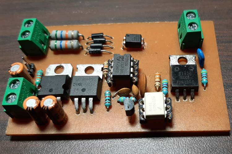
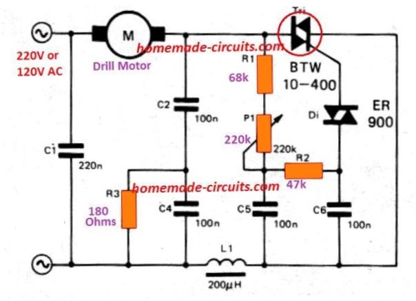
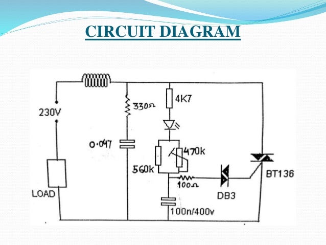
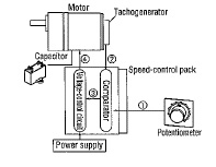
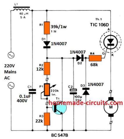
AC Motor Speed Controller Circuit. This triac-based 220V AC motor speed controller circuit is designed for controlling the speed of small household motors like drill machines. The speed of the motor can be controlled by changing the setting of P1. The setting of P1 determines the phase of the trigger pulse that fires the triac. In this paper, the characteristics of single-phase line-start permanent magnet synchronous motor driven by constant voltage are analyzed on d-q axis vector diagram and compared with that of current... This shows how the tachogenerator is used during motor operation. Since the control circuit is much less complex than a VFD, AC speed control motors are a cost-effective option vs VFD-driven AC motors. The phase control method also exhibits less electrical noise when compared to VFD-driven motors, where VFDs switch at a much faster rate. A very common form of latch circuit is the simple "start-stop" relay circuit used for motor controls, whereby a pair of momentary-contact pushbutton switches control the operation of an electric motor. In this particular case, I show a low-voltage control circuit and a 3-phase, higher voltage motor: L1 L2 M1 M1 Start Stop M1 motor To 3 ...
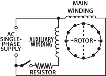
meter diagram. The user of this meter views the ends of all those unequal length reeds as they are... tank circuit (parallel inductor and capacitor). See Figure below. One or both components are made adjustable... If we have access to an accurate frequency standard (a source of AC voltage holding very precisely to a single... The following fig shows the stator and rotor of a 1-phase induction motor. Single-phase AC supply is given... The connection diagram is as shown in the above figure. The current flowing through the main winding is I... synchronous speed, the centrifugal switch opens. So, the auxiliary winding is out from the circuit. And motor... This basic phase triggering circuit uses the triac in series with the motor across an AC sinusoidal supply. The variable resistor, VR1 is used to control the amount of phase shift on the gate of the triac which in turn controls the amount of voltage applied to the motor by turning it ON at different times during the AC cycle. In a single phase AC circuit there is one "feeding" and one returning path. The two wires making the paths have the same loss of energy due to resistance because... AC-motor Speed control Different kind of machines, ie conveyors, pumps and fans are usually designed to run at constant speed provided by AC induction motors. Some...
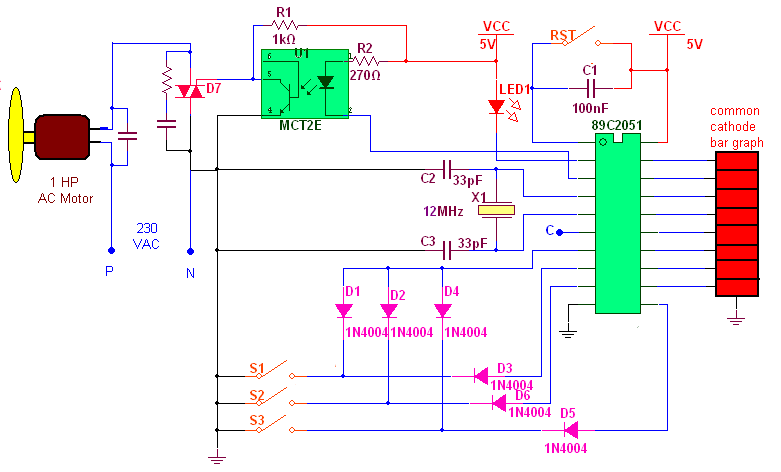
Single phase AC Motor speed controller
Install a variable rheostat and you can control your motor's speed. Disconnect the single-phase motor from the power source. Use a knife and cut the wire that connects the motor to the power source. Make the cut about 12 to 18 inches away from the motor. Cut off about 2 inches of outer plastic from the two cut ends of wire using wire strippers.

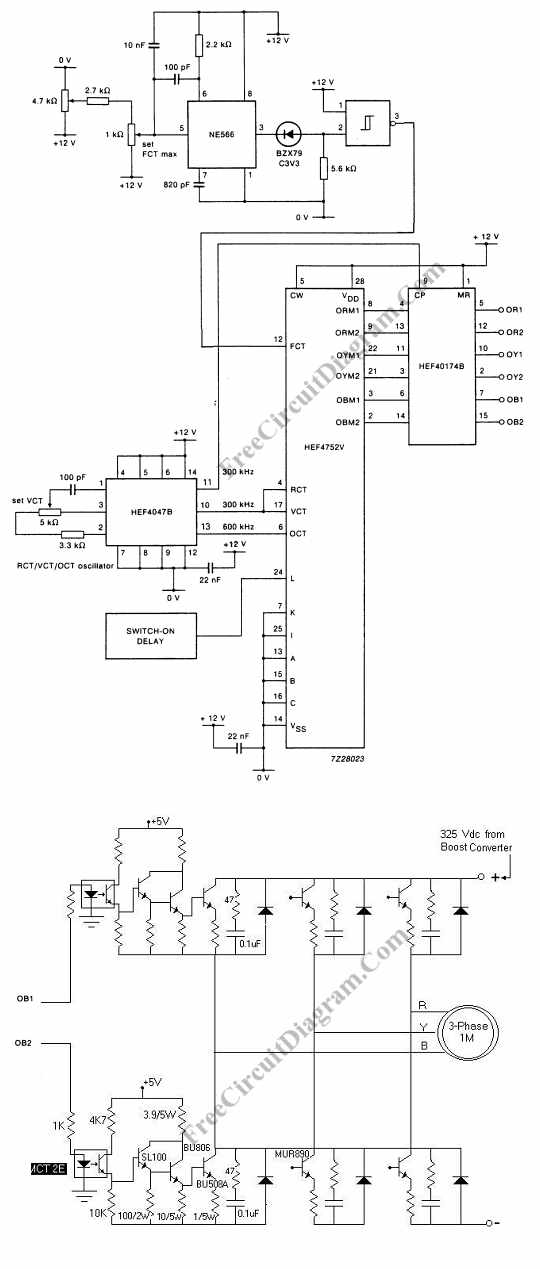
Gate drives circuit *source from DVB Journal, PIC Based Speed ...
Diagram DD5 TWO-SPEED MOTORS For all other SINGLE-PHASE wiring diagrams refer to the manufacturers data on the motor. Diagram DD6 Diagram DD7 M 1~ LN E Diagram DD8 LN E L1 L2 L3 S/C Z1 U2 Z2 U1 Cap. Thermal contacts (TB) white M 1~ Z2 - Yellow Z1 - Blue U2 - Black U1 - Red Bridge L1 and L2 if speed controller (S/C) is not required M 1~ LN E ...
![Penulis Elex: [41+] Draw The Schematic Diagram Of Scr Based ...](https://blogger.googleusercontent.com/img/b/R29vZ2xl/AVvXsEilhzYPt_wvqi9039rqHTaYg-IZdF-N06G3nVu0NRN4Yzsmoorp-FSHfxeUsYfxNEP9dRp6il6XrtiqcpJ5016gsaxfW_nSKbjpYDukDnkSQZjYoNHYYQnsCS0_2uN8wo4fd_hve8vIjKg/s1600/Speed-Control-Of-Ac-Motor-Using-Scr2.jpg)
Penulis Elex: [41+] Draw The Schematic Diagram Of Scr Based ...
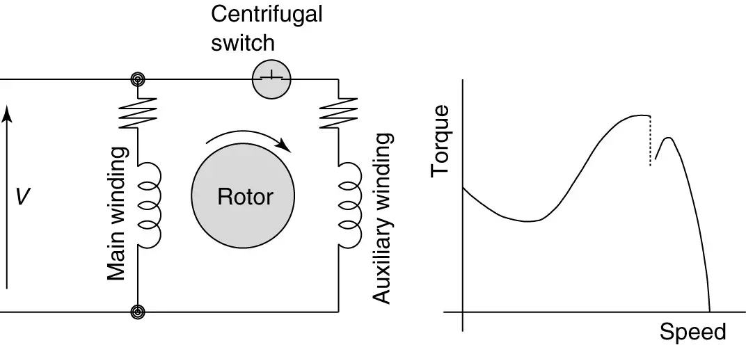
FIGURE 2: Capacitor-start induction motor (CSIM) circuit (wiring) diagram and torque-speed curve. Single-phase motors are inherently noisier and less smooth running than polyphase motors. Because there is a backward-rotating component of flux, there are pulsating torques, so the torque-speed curve is really just a representation of the average ...

Closed Loop Single Phase AC Motor Speed Controller Circuit ...
Single phase AC Motor speed controller. December 22, 2012 By Ashutosh Bhatt. Here is a very simple example of AC motor speed control given by changing firing angle of TRIAC with the help of micro controller 89C2051. Varying speed of AC motor by means of changing firing angle of any thyristor is very widely used method.
Jupiter AC 220V SS-22 50/60Hz Motor Speed Controller 90 ...
Split Phase Single Value Capacitor Electric Motor (Dual Voltage Type). Split Phase Single Value Capacitor Electric Motor (Dual Voltage Type). This motor has two identical main winding's arranged for either series or parallel connections. With the main winding's connected in parallel, the line voltage is usually 240.

AC Motor Speed Controller Circuit Using AT89C51
This figurecould either be two paralleled and synchronized alternators driven by a mechanical energy source, or an alternator driving a synchronous motor. Or, it could be two motors, if an external power source were connected. The point is that in either case the rotors must run at the same nominal frequency, and be in phase...
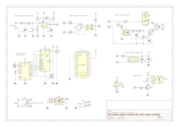
Arduino-Based Universal AC Motor Speed Controller - Arduino ...
The ac voltage controllers are classified into two types based on the type of input ac supply applied to the circuit. ☞Single Phase AC Controllers. ... ☞Speed control of induction motors (single phase and poly phase ac induction motor control). ... ☞The connections are made as per the circuit diagram given above. ☞The R Load must be 60W ...
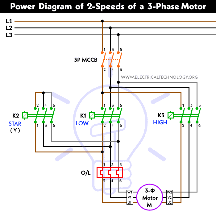
2 Speeds 1 Direction 3 Phase Motor Power and Control Diagrams
Capacitor start capacitor run induction motors are single phase induction motors that have a capacitor in the start winding and in the run winding as shown in figure 12 and 13 (wiring diagram). This type of motor is designed to provide strong starting torque and strong running for applications such as large water pumps.

Single Phase AC Motor - STMicroelectronics
Instructions on how to remotely control the vfd vid covers wiring in start cw stop start ccw and speed control. Vfd drive wiring diagram. 1 the vfd s three phase ac input terminals r l1 s l2 t l3 the power line s input terminals connect to 3 phase ac power through line protection or leakage protection breaker it does not need to consider the ...
AC Phase Angle Control for Light Dimmers and Motor Speed ...
driver circuit (such as in a brushless or stepper motor). When it comes to the naturally alternating... Single-Phase AC Motors Inside a single-phase motor, the main drive coil is actually a series of coils... of motor is that a three-phase supply must be present to drive such a motor. With modern control systems, this is... motor control motors three phase motor single-phase ac motor single... Products Circuit Protection Connectors...
3 Phase AC Motor Speed Control – Electronic Circuit Diagram
These nice little speed controllers will control your single phase motors in either 120v or 240v. All models feature single-phase AC input and fully variable AC output. The enclosed version comes with a rugged housing, power on/off switch, power on indicator lamp, front access fuse, as well as convenient input and output cords and plugs.

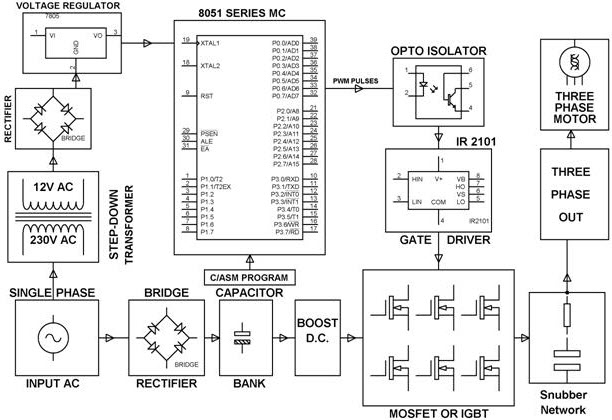
Block diagram of Automatic Speed Control of Single Phase ...
Sep 25, 2021 · Triple Rate Motor Connection. Single Phase Capacitor Motor Wiring Diagram – Single phase motor wiring diagram with capacitor start. Interconnecting wire routes may be shown approximately where particular receptacles or fixtures must be upon a common circuit. Motor 3ct to 120 v separate control ot is a.
3 Phase AC Induction Motor working and its Controlling using ...
Sep 15, 2013 · I have to control a pump driven by an induction asincron motor, single phase 220V AC, 200w. The motor is sealed and the only „connection” to it is the 3-wire cable: line, null and earth. The VFD has to run between 20 Hz (say LF) and 50Hz (say HF). The time to increase from LF to HF is variable depending the application (up to minutes).
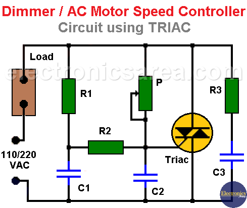
Dimmer / AC Motor Speed Controller Circuit using TRIAC ...
This paper deals with fault-tolerant control of five-phase induction motor (IM) drives under single-phase open. By exploiting a decoupled model for five-phase IM under fault, the indirect field-oriented control ensures that electromagnetic torque oscillations are reduced by particular magnitude ratio currents. The control...

Speed Control of Single Phase Induction Motor Using Single ...
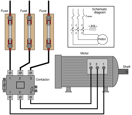
The control circuit is separate from the motor circuit. The control circuit may not be at the same voltage as the power circuit. When the voltage of the control and power circuits is the same, it is referred to as Common Control. If the volt-ages are different, it is called Separate Control. Figure 4. Typical Starter Wiring Diagram — Three-Phase

Starting methods of three phase induction motors ...
Perhaps one operator turned the motor off and wants to perform maintenance. There should be a single location from which the entire control or power circuit can be disabled and locked out. This circuit adds a switch or... In the diagram, simply replace the relay coil with the starter coil and use aux contacts instead of relay... control motor control circuit three phase motor advanced motor control Share Comments 0 Comments Log in to...
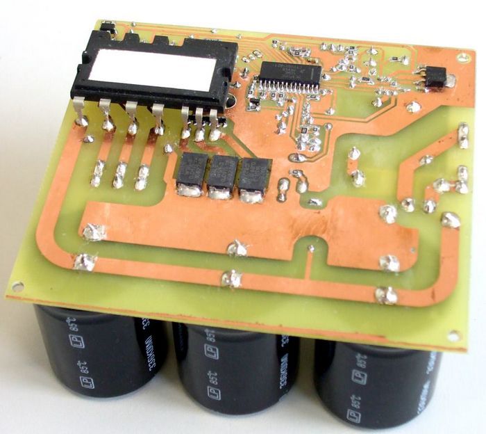
1000W AC Motor Speed Controller
Single-Phase Series Motor (Universal) The single-phase series motor is a commutator-type motor. If the polarity of the line terminals of a dc series motor is reversed, the motor will continue to run in the same direction. Thus, it might be expected that a dc series motor would operate on alternating current also.

AC Motor Speed Controller Circuit
Every large motor requires a circuit to turn it on and off. This may be as simple as a single on/off drum... three-phase motor requirements. If the motor needs to drive forward and reverse, or if it needs a variable speed control, then there must be a specific circuit used to drive such an application.It is not recommended to...

ACPWM control System for Induction Motor using pic ...
The "AC speed control motor unit" that uses the most popular single-phase capacitor-run induction motor... motor & gear motors Brushless DC motor & gear motors The output control method of a speed control circuit can... 9 shows the configuration of the speed control system for an AC speed control motor in a block diagram. Fig....

THREE PHASE INDUCTION MOTOR SPEED CONTROL
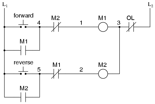
Single phase motor control circuit. Single phase AC Motor speed controller. The key to understanding the purpose of an overload heater is found by examining the single-phase L1 L2 control circuit where a normally-closed switch contact by the same name OL is connected in. These are classified into different types but the.

3 Phase Induction Motor Speed Controller Circuit - Electronic ...
The motors wiring diagram on the underside of the junction box is badly faded part of it reads t1 t2 are the at leads. Single phase three phase wiring diagrams 1 phase 3 phase wring the star delta y d 3 phase motor starting method by automatic star delta starter with. We hope this helps further your understanding of motor controls.

Ceiling Fan Speed Control Switch Wiring Diagram
Interpret this AC motor control circuit diagram, explaining the meaning of each symbol: Also, explain the operation of this motor control circuit. What happens... The key to understanding the purpose of an overload heater is found by examining the single-phase (L1 / L2) control circuit, where a normally-closed switch contact by...
Closed Loop AC Motor Speed Controller using Back EMF ...
Our new YouTube channel - https://goo.gl/zSp9xcThe device is designed to adjust the speed of an electric motor running on alternating current. In the engine ...
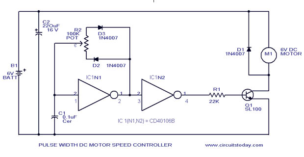
PWM Motor Speed Control Circuit with Diagram for DC Motor
I'm in a project similar to the OP, and also need to control the speed of a single phase motor. Actually what I need to control is air flow through motor speed. The motor plate is in the attached file, following is a summary of the most relevant data Single phase, 220v AC, 60hz, ~3.25A The motor is from an old Buchi 710 fluid bed dryer

Motor Speed Control
A method for the fault-tolerant vector control of star-connected 3-phase Induction Motor (IM) drive systems based on Field-Oriented Control (FOC) is proposed in... The proposed drive system significantly reduces the speed and torque pulsations caused by an open-phase fault in the stator windings. The performance of the proposed...
Types of Single Phase Induction Motors | Single Phase ...
Aug 03, 2020 · The article presented here explains a very simple closed loop AC motor speed controller circuit that may be used for controlling single phase AC motor speeds. The circuit is very cheap and uses ordinary electronic components for the required implementations. The main feature of the circuit is that it’s a closed loop type, that means the speed ...
3 Phase AC Motor Controller - Electronics-Lab.com
With Single Phase Motor with Capacitor forward and Reverse Wiring. Diagram DD6 Diagram DD7 M 1~ LN E Diagram DD8 LN E L1 L2 L3 S/C Z1 U2 Z2 U1 Cap. A wiring diagram gives the necessary information for actually wiring-up a group of control devices or for physically tracing wires when trouble-shooting is necessary.
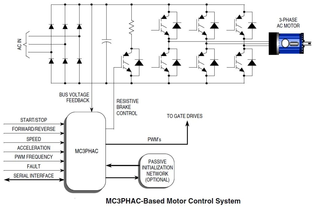
Three Phase Motor Control Circuit MC3PHAC FSBS10CH60 ...
Ceiling Fan Speed Control, Rev. 0 Solution 2 Freescale Semiconductor 2Solution 2.1 Single Phase Induction Motor Control Theory Single-phase induction motors are th e most used. These motors have onl y one stator wind ing, operate with a single-phase power supply, and are also squirrel cage. Because of the single phase, the motor is not

3 Simple DC Motor Speed Controller Circuits Explained
I have a fairly solid background in industrial AC motor control (soft starters, VFDs, etc.) but something that I'm certainly NOT well versed in is brushless DC... star-connected AC induction motor, and the motor controllers look to be very, very similar to the typical three-phase AC controllers I've spent most of my...
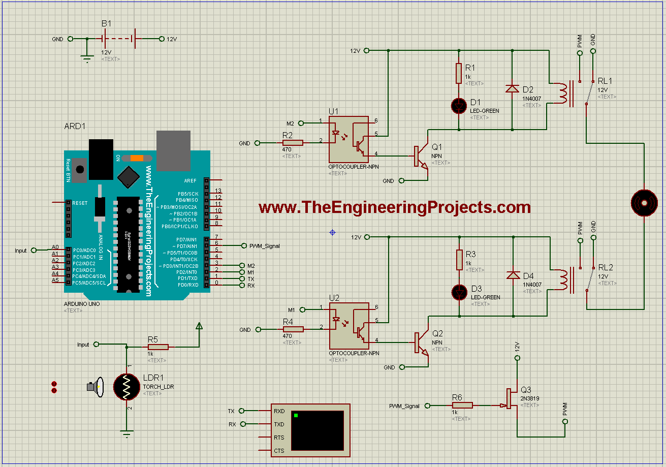
DC Motor Speed Control using Arduino in Proteus - The ...
Bodine Electric Company is a leading manufacturer of fractional horsepower gearmotors, motors, parallel shaft gearmotors, and motor speed controls. Bodine Electric offers over 1,300 standard products
Speed Control Of Single Phase Induction Motor

Electronic AC 220V SS-22 50/60Hz Motor Speed Controller 90 ...
Speed Control of Single-Phase Induction Motor - Electrical ...
AC Motor Control Circuits Worksheet - AC Electric Circuits
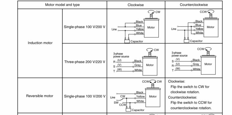
Speed Control Methods of Various Types of Speed Control Motors
MOTOR CIRCUITS AND CONTROL – Applied Industrial Electricity

90W Single Phase AC Gear Motor, Speed Control
Closed Loop AC Motor Speed Controller using Back EMF ...

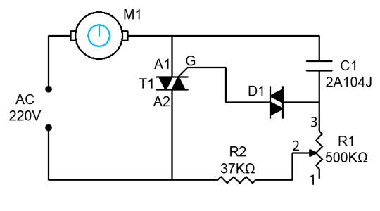
Speed Control of Fan Motor using Diac and Triac

AC 220V 50/60Hz Single Phase AC Motor Speed Controller Electric Motor Speed Regulator
AC Motors Part 3-Single Phase Operation | Pumps & Systems


Comments
Post a Comment