43 lewmar windlass wiring diagram
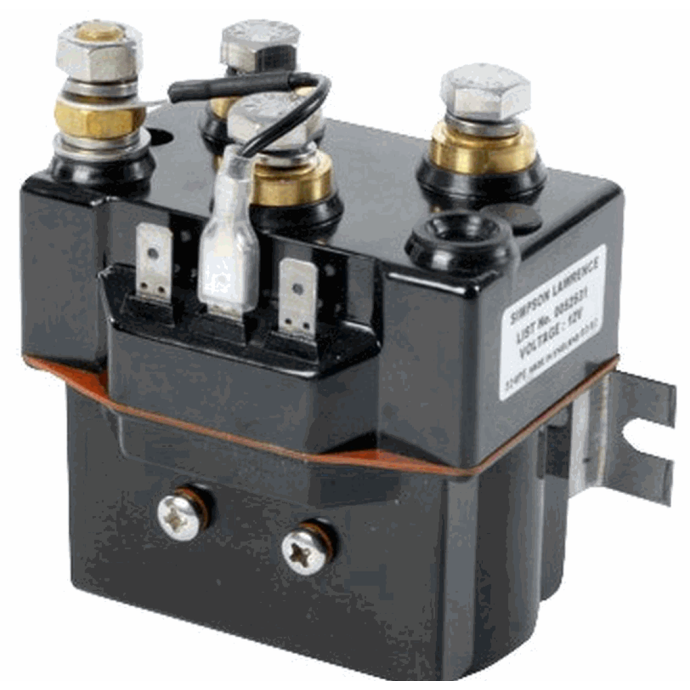
Jun 17, 2021 · 20210617_89E11A01C118FAE4!!!! - Free download as PDF File (.pdf), Text File (.txt) or read online for free. Save More on Your Lewmar #0052531 Windlass Single & Dual Direction Sealed Solenoids , PM ( for ) All Horizon Series; Sprint 600 & 1000 at Fisheries Supply. Excellent Customer Service, Ready to Ship. Marine Supplies Since 1928!
Lewmar windlasses are designed and supplied for anchor control in marine applications and are not to be used ... 5.4 V700 Wiring diagram (toggle switch).20 pages
Lewmar windlass wiring diagram
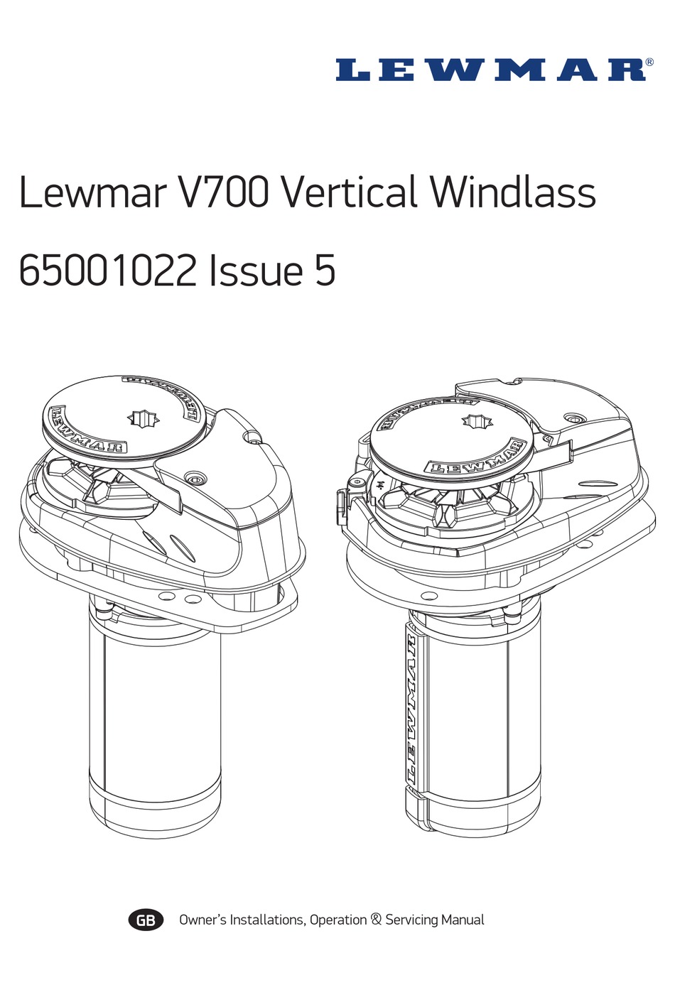
This will bypass both the switch and solenoid wiring the windlass motor directly to the power source. Do this for troubleshooting only to test that the solenoid is the only problem. Step 3: Use a voltmeter to check for voltage at the windlass motor. Put the positive probe on the electrical stud on the motor, the negative probe on There are two types of electric anchor windlasses: horizontal-gypsy models with the unit fully enclosed above deck and vertical-gypsy models with much of the unit concealed below deck. Both automaticaly feed line and chain into the rode locker. We chose the Pro-Fish 1000 horizontal windlass from Lewmar , which has a free-fall function. This ... Lewmar V700 Vertical Windlass ref 65001022 iss.8 | 7 CABLE SIZING FOR LENGTH OF CABLE RUN 0 - 10 m 0 - 33 ft 11 - 18 m 34 - 60 ft 19 - 24 m 61 - 80 ft 10 mm2 8 AWG 16 mm2 6 AWG 25 mm2 4 AWG 5. Electrical wiring 5.1 Electric cable selection Plan the installation to suit the controls and give the operator a full view of the windlass. The wiring ...
Lewmar windlass wiring diagram. 1.6 Fitting the windlass to the deck 5 1.7 Fitting the motor gearbox 7 2. Electrical wiring installation 8 2.1 Electric cable selection 8 2.2 Wiring 8 2.3 Control switch installation 8 2.4 V1 Wiring diagram 9 3. Operating your windlass 10 3.1 Safety fi rst 10 3.2 Use of clutch 10 3.3 Letting go under gravity 10 3.4 Letting go under power 10 When the windlass is not in use the anchor must be tied off onto a cleat or equivalent strong point to ... Concept/Ocean/Capstan 2 & 3 Wiring Diagrams.26 pages Lewmar Windlass Wiring Diagram- One of the most hard automotive repair tasks that a mechanic or repair shop can take is the wiring, or rewiring of a car's electrical system.The pain really is that every car is different. taking into account trying to remove, replace or repair the wiring in an automobile, having an accurate and detailed lewmar windlass wiring diagram is critical to the ... Lewmar Windlass Wiring Diagram Name, Volt, Used on, Download wiring diagram Series Wound Dual Direction Contactor - /, 12/24V DC, Concept 3, V4 Windlass, Click here. Propose using lewmar dual direction contactor. The contactor has Wiring diagram for windlass shows 4 posts on contactor. Is it the case then. Pre & Custom Build Models.
1.6 Fitting the windlass to the deck 5 2. Electrical wiring installation 7 2.1 Electric cable selection 7 2.2 Wiring 7 2.3 Control switch installation 7 2.4 V700 Wiring diagram (toggle switch) 8 2.5 V700 Wiring diagram (contactor) 8 3. Operating your windlass 9 3.1 Safety fi rst 9 3.2 Use of clutch 9 3.3 Letting go under gravity 9 Lewmar REVO™ Winch Manual ref B10489 iss.3 | 7 4.1 Wiring Plan the installation to suit the controls and give the operator a full view of the winch. The wiring system should be of the fully insulated type, which avoids possible electrolytic corrosion problems. We recommend the use of type III stranded, tinned copper wire with copper crimp ... 5.5 V1-6 Wiring diagram. Installation instructions are supplied separately with any accessories. 1. NOTE: Motor connections. At P2 Marine we understand that when you need a part for your Lewmar windlass, you need it delivered quickly. This is why we stock all of the most common parts required to keep your windlass in service, and we place weekly orders to fill in for less common and special order parts.
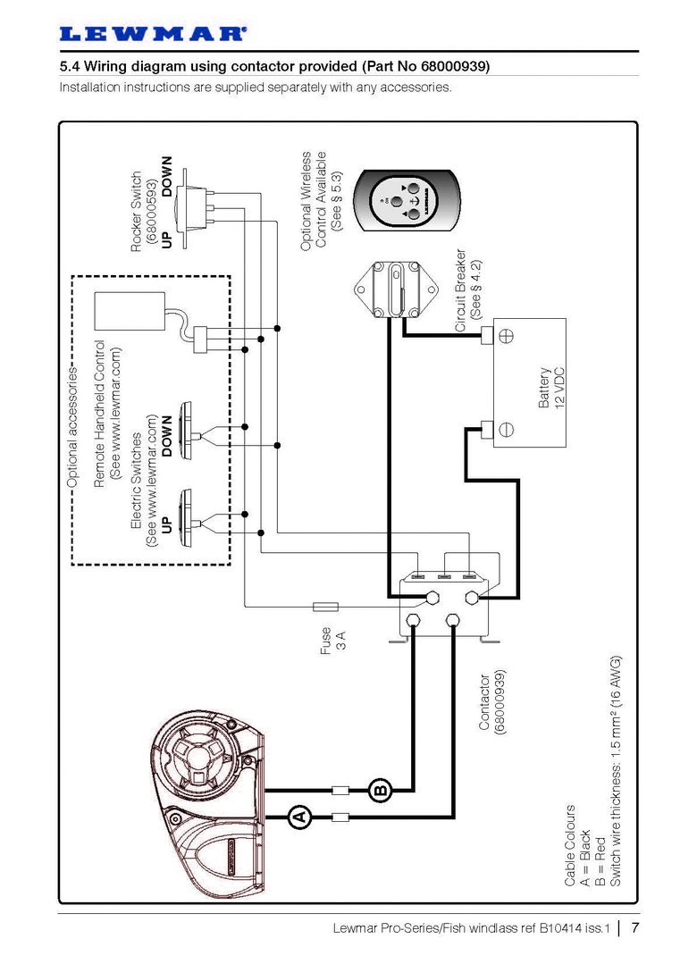
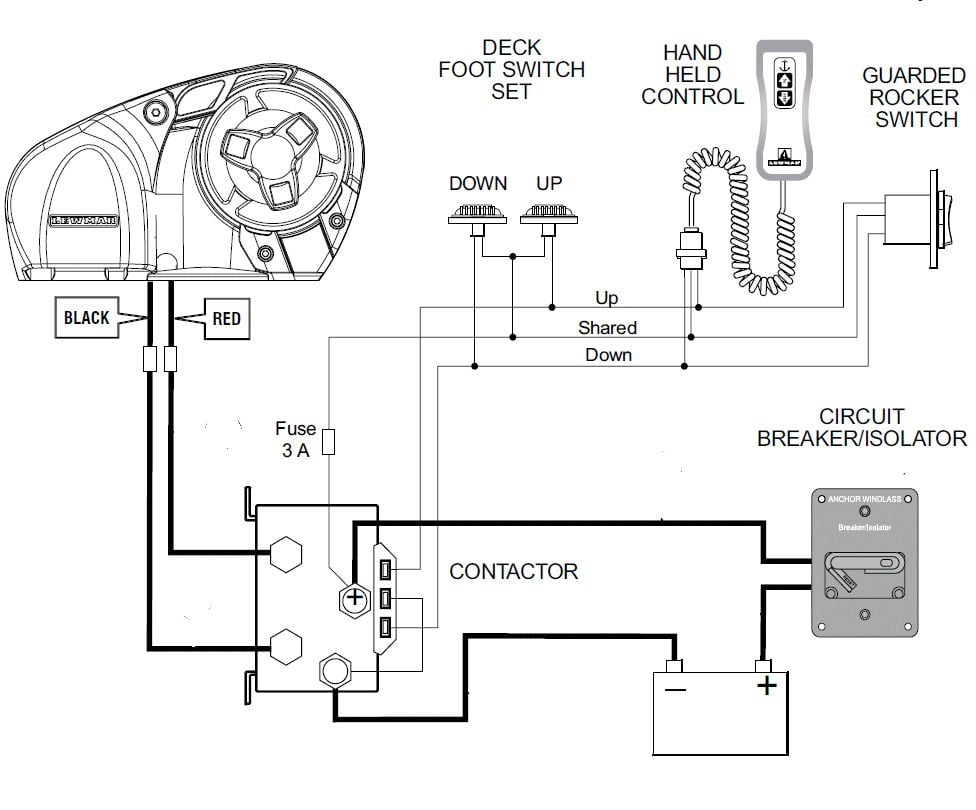
Lewmar Pro-Series/Fish windlass ref B iss.1 Page 8. Wiring diagram if a contactor box (Part No ) is used Installation instructions are supplied separately with any accessories. Page 9. Wiring diagram if a pre-wired control box (Part No ) is used Installation instructions are supplied separately with any accessories. Lewmar Windlasses. RECOMMENDED WIRING DIAGRAMS FOR LEWMAR. PRODUCTS: ... Wiring Diagram 12VDC. Used on: Pro-Sport, ... For Terminals 1 to 5. Refer to windlass wiring. Diagrams.10 pages Issue #3: Your Electric Windlass Motor is Running but the Chainwheel Doesn't Turn. If the windlass motor runs, but the windlass isn't deploying or retrieving the anchor rode, the most common issue is with the clutch adjustment. Most windlasses have a clutch adjustment, which when loosened allows the chain to freefall. PDF. Postcolonial Studies in the Twenty-first Century: A Book Review Article of Literature for Our Times & Reading Transcultural Cities Alejandra Moreno Álvarez
1. 2. GREY. BLUE. Lewmar windlasses are designed and supplied for anchor control in marine applications and are not to be . Wiring diagram using contactor provided ( Part No ) .. Is there voltage at the positive switch terminal on the solenoid. If your windlass is reversing it simply has an additional footswitch, solenoid .
Can be used with all Lewmar custom windlasses, contact the sales office for a specific wiring diagram. Sprint 900, Atlantic, Atlantic A, Atlantic C, AP700, AP1000 & AP1200 : Use Diagrams A* or B Atlantic B & Concept / Ocean2 : Use Diagrams C or D - Sprint 3000 : Use Diagrams C or E *Contactor 0052531 is NOT suitable for these products.
It appears that #4 guage wire runs from battery/circuit breaker to "contactor" then to motor it is probably #10 wire, 3 or 4 ft. The rocker switch clicks in one positio … read more. V700 lewmar windlass. Conected to a lewmar contactor.
About Press Copyright Contact us Creators Advertise Developers Terms Privacy Policy & Safety How YouTube works Test new features Press Copyright Contact us Creators ...
Lewmar V700 Vertical Winlass ref 65001022 iss.4 | 7 CABLE SIZING FOR LENGTH OF CABLE RUN 0 - 10 m 0 - 33 ft 11 - 18 m 34 - 60 ft 19 - 24 m 61 - 80 ft 10 mm2 8 AWG 16 mm2 6 AWG 25 mm2 4 AWG 5. Electrical wiring 5.1 Electric cable selection Plan the installation to suit the controls and give the operator a full view of the windlass. The wiring system
Wiring • Plan wiring installation to suit controls and to give operator full view of windlass. • Use marine grade copper wire. • Fit copper crimp terminals to wire ends. • Keep windlass wiring separate from other wiring, and connect to starter battery where possible. • The circuit breaker must be kept dry. • All switches must be ...
Lewmar v700 2. Electrical wiring installation . 6V700 Windlass 7, 2. Electrical wiring installation, +, E, A, 2.1 Electric cable selection, 2.2 Wiring, 2.3 Control switch installat ion, 2.4 V700 Wiring diagram (t oggle switch), 3.1 Safety rst, 3.2 Use of clutch, 3.3 Letting go under grav ity
Jamestown Distributors TV: Retro-Fitting A Lewmar Windlass: Wiring the Control Box. Power and Motoryacht Magazine's Ken Kreisler and Lewmar's Tom Fleming pr...
Follow the wiring diagram § 5.5 NOTE: • Optional electric footswitches and remote handheld control available. Visit www.lewmar.com for more information • Contactor box and control box used in some installation refer to wiring diagram § 5.6 and § 5.7 • Optional wireless remote also available. See table below for models and references
a aa aaa aaaa aaacn aaah aaai aaas aab aabb aac aacc aace aachen aacom aacs aacsb aad aadvantage aae aaf aafp aag aah aai aaj aal aalborg aalib aaliyah aall aalto aam ...
The boat's wiring harness and the panel are connected together at the wiring block strip using a series of plugs from each that snap onto opposite sides of the wiring block strip. Page 104 6/12/2008 9:12 AM 13.12.9.
• Contact Lewmar for correct fi tting of electrical connections. If the motor is unitentionally fi tted this way on a single speed winch it will not operate and make a clicking noise, on a 2 or 3 speed winch it will dramatically reduce performance. • Check clearance below deck and accessibilit y then position the
Hello, I am installing a Lewmar 700H Pro Series Windlass on a 21' CC. My batteries are in the console, so the wire length will be approx 18' to 20'. I am planning to use ANCHOR tinned wire in the 4-AWG size. The installation guide recommends to use 8-AWG size, but West Marine recomends to use 2-AWG size.
Lewmar CPX Vertical Windlass 66300104 Issue 2 D Installations-, Betriebs- und Wartungshandbuch F ... Electrical Wiring 14 ... 4.3 Control switch installation 15 4.4 Wiring diagram 16 5. Operation 17 5.1 Braked anchor free-fall 17 5.2 Power up/down 18 5.3 Optional manual recovery kits 19
Wiring diagram using contactor provided ( Part No ) .. Is there voltage at the positive switch terminal on the solenoid. Pre & Custom Build Models. Can be used with all Lewmar custom windlasses, contact the sales office for a specific wiring diagram. Sprint , Atlantic. If your windlass is reversing it simply has an additional footswitch, solenoid .
2.4 V700 Wiring diagram (toggle switch) ... With a Lewmar windlass you will be provided with ... Lewmar windlasses are designed and supplied for anchor.9 pages
Wiring Diagram 12/24VDC Used on: 140TT2.2KW; All 185TT, 250TT, 300TT To Thruster Black box Via Automatic Battery switch if fitted and/or P/S Battery switch if fitted 3 4 1 2 GREY BLUE RED BLACK GREY(BLACK-3) BLUE(BLACK-2) RED(BLACK-1) BLACK(GRN/YELL) 5432 1 5 BUTTON WIRELESS RECEIVER MODULE 68000968 876 For Terminals 1 to 5 Refer to windlass ...
Lewmar Windlass Wiring Diagram Upgrade Windlass Power Wiring Of Lewmar Windlass Wiring Diagram With Windlass Wiring Diagram For Windlas Diagram Power Wire Wire . How To Read Automotive Wiring Diagrams In 2021 Electrical Circuit Diagram Diagram Electrical Symbols . Automotive Cooling Wiring Diagram In 2021 Car Mechanic Electricity Automotive
Looking at Ralph wire diagram, it looks like he tapped off from the main power cable. Actually, that is the wiring diagram from the Lewmar installation instructions. Here's my as-built wiring. Seeing as I already had a 5A breaker for the windlass on my panel, I thought I'd use it as a...
The Institute comprises 33 Full and 14 Associate Members, with 16 Affiliate Members from departments within the University of Cape Town, and 17 …
• Lewmar windlasses are designed and supplied for anchor control in marine applications and are not to be used in conjunction with any other use. • Keep limbs, fingers, clothing and hair clear of windlass, rode and anchor during operation. ... Figure shows a typical installation wiring diagram. ...
The first step towards benefiting from the Netstrata difference is to make an enquiry for an obligation free quote. Request a Quote. If you would like to …
Lewmar V700 Vertical Windlass ref 65001022 iss.8 | 7 CABLE SIZING FOR LENGTH OF CABLE RUN 0 - 10 m 0 - 33 ft 11 - 18 m 34 - 60 ft 19 - 24 m 61 - 80 ft 10 mm2 8 AWG 16 mm2 6 AWG 25 mm2 4 AWG 5. Electrical wiring 5.1 Electric cable selection Plan the installation to suit the controls and give the operator a full view of the windlass. The wiring ...
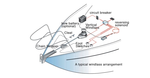
There are two types of electric anchor windlasses: horizontal-gypsy models with the unit fully enclosed above deck and vertical-gypsy models with much of the unit concealed below deck. Both automaticaly feed line and chain into the rode locker. We chose the Pro-Fish 1000 horizontal windlass from Lewmar , which has a free-fall function. This ...
This will bypass both the switch and solenoid wiring the windlass motor directly to the power source. Do this for troubleshooting only to test that the solenoid is the only problem. Step 3: Use a voltmeter to check for voltage at the windlass motor. Put the positive probe on the electrical stud on the motor, the negative probe on











Comments
Post a Comment