42 led dimmer circuit diagram
› wiring-devices › light-switches-andradiant® CFL/LED Dimmer | Dimmers | Light Switches and ... Oct 31, 2018 · This dimmer designed for use with most compact fluorescent and LED dimmable screw-in bulbs. Most recessed can LED's have a built in or external driver and we would recommend the universal dimmer(RH703PTUTC) for that type of lighting. You can try using the calibration wheel on the RHCL453 dimmer to adjust the low end trim(see instructions). › 2019/05/1-15-minute1 to 15 Minute Timer Circuit Diagram, Working and Applications May 01, 2019 · The above circuit diagram is for the 1-minute timer circuit. For 5 min, 10 min and 15 min you just have to change the resistor value (R 1). 1 Minute Timer Circuit: We have to configure 555 Timer in Mono-Stable mode to build a timer. The 555 Timer starts timing when switched ON. After one minute of time duration, the LED will automatically turn ON.
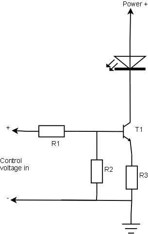
Led Dimmer Circuit Diagram | Circuit Diagram Images gallery of led dimmer circuit diagram. LED Dimmer Circuit Electronic Projects Circuits. This is a very simple LED dimmer circuit which has 2 transistors, 1 resistor and 2 potentiometers. Typical segment displays LEDs consume around 25 mA for e. Light Dimmers Elliott Sound Products The...

Led dimmer circuit diagram
220V AC Light/Fan Dimmer using TRIAC & Arduino Here is a circuit diagram for 220V AC Light Dimmer/Fan Speed Controller using TRIAC & Arduino. The schematic has been designed using EasyEDA online PCB Designing tool. After that you can solder all the necessary components as per circuit diagram and make the final product ready. Fan Regulator Circuit, AC Lamp Dimmer, Ceiling Fan Electronic... This is 220v ac dimmer circuit diagram based on capacitor, in the capacitive Dimmer/regulator no noise.Resistor, One Capacitor, One Diac And One Triac. TRIAC is a semiconductor device belonging to the family of thyristors. LED Dimmer Circuit - Lighting | Led dimmer, Electronics circuit... PWM based LED Dimmer Using 555 - Circuit, Block Diagram, Working. Read this post to get knowledge about circuit diagram and working of PWM LED Dimmer Using 555 Timer IC. Here, we use PWM Technique to dim the intensity of light of the LED using 555 Timer IC.
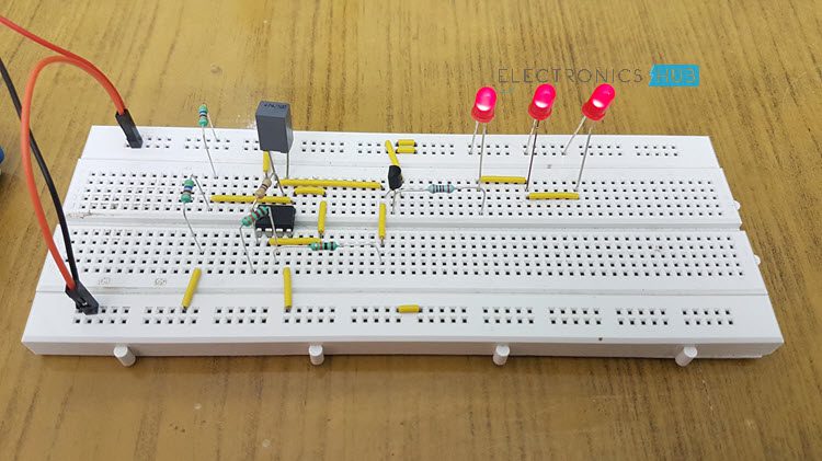
Led dimmer circuit diagram. 20 Watt LED Dimmer Circuit diagram | Electronics Forums I want to design 20 watt led dimmer circuit diagram so can any one please provide me PCB diagram so that i will make PCB and assemble it. Your homemade diagram is much better than your 'other' design. But you have to know the specifications of your leds. Are they 3.5v and 350ma each? PWM LED Dimmer Circuit Diagram using IC 555 Timer The LED DIMMER is primarily a 555 IC based PWM (Pulse Width Modulation) circuit developed to get variable voltage over constant voltage. The circuit is connected in breadboard as per the circuit diagram shown above. However one must pay attention during connecting the LED terminals and the... PWM LED dimmer circuit using IC 555 - Gadgetronicx Working of PWM LED dimmer circuit: 555 timer IC a widely used one was used to generate the PWM signal here. Here the IC was wired as an Astable Multivibrator which gives square wave pulses as output in pin 3. The output frequency of the the Multivibrator was governed by the values R2, RV1 and... LED Dimmer Circuit | Circuit Diagram FM Transmitter Circuits. Store. Circuit Diagram. Copyright 2013 © CircuitDiagram.Org. All rights reserved. LED Dimmer Circuit. Sponsored Links. View full size image. Related Circuits.
uwiring.com › arduino-wiring-diagram-makerArduino Wiring Diagram Maker - U Wiring Nov 08, 2021 · Arduino Circuit Diagram Maker. Arduino Wiring Diagram Creator Posted by Margaret Byrd Posted on November 22 2019. Arduino Joystick Thumbstick Module Wiring Diagram Arduino Joystick Arduino Stepper To draw arduino circuit schematic drawing an diagram. Arduino wiring diagram maker. Circuitoios online circuit builder gives you wiring code and IoT solutions for Arduino projects. Encouraged for […] led dimmer circuit 3d models 【 STLFinder 】 l led dimmer circuit 3d models. This is a reproduction of the (fairly) common 90W LED Dimmer circuit that...Replacement backplate for an inexpensive LED dimmer control (see link) that allows it to be easily...The circuit diagram and the firmware (ATtiny85) for the dimmer can be found [here](http... LED Dimmer Circuit Diagram | EdrawMax Editable Templates LED dimmer is a device that helps us to increase and decrease the brightness of a power LED. Generally, it contains a potentiometer through which we can adjust the output voltage which affects the brightness of an LED. So here we create a circuit of led dimmer by using a 555 timer IC. Diagram schematic Dimmer light switch circuit - Xtronic Dimmer light switch circuit with Triac, potency control in loads as illumination of bulb. Dimmers are devices used to lower the brightness of a light. Dimmer switches for LED lights (dimmable) and Incandescent bulb. Diagram schematic Dimmer light switch circuit.
Simple & Easy Dimmer Circuit Using 555 IC for LED... - Instructables To build your own Dimmer Circuit using 555 IC you can watch the video embedded in this step or continue reading. Construct the circuit diagram as shown in the circuit diagram. The circuit should be powered above 10 volts & the voltage should not exceed more then 14 volts. Dimmer for LED circuit diagram Dimmer, Linear,. Parallel to Series. LED Driving Circuit. Automatic LED display dimmer using a LED as a light sensor. LED dimmer circuit dimming circuit schematics free electronic circuits diagram wiring design plans schema DIY projects handbook guide tutorial schematico electrónico... 555 Led Dimmer Circuit IRFZ44 - Electronics Projects Circuits The Led dimmer circuit you see in the diagram works like a DC dimmer, the brightness of a number of led groups can be increased or decreased. Electronics Projects, 555 Led Dimmer Circuit IRFZ44 "555 timer circuits, power electronic projects, " Date 2019/12/08. circuitdigest.com › electronic-circuits › t-flipT Flip Flop Circuit Diagram, Truth Table & Working Explained Oct 02, 2017 · T Flip-flop Circuit diagram and Explanation: The IC power source V DD ranges from 0 to +7V and the data is available in the datasheet. Below snapshot shows it. Also we have used LED at output, the source has been limited to 5V to control the supply voltage and DC output voltage. We have used a LM7805 regulator to limit the LED voltage.
Simple LED Dimmer Circuit
Light Dimmers A complete circuit diagram is not especially useful for a trailing edge dimmer, because they generally use dedicated integrated circuits (or fairly complex circuits using more common ICs) to The dimmer has a circuit to detect the spike, and if detected it will switch from trailing edge to leading edge mode.

How to make LED bulbs dimmable - EDN
220 V AC Light Dimmer Circuit Diagram, Fan Regulator Circuit This is the simplest Light Dimmer Circuit Diagram or Fan Regulator Circuit Diagram. The circuit is based on the principle of power control using a Triac.The circuit, and design are the same For Fan or Light the only difference is the output load to be varied, that is, fan or light.

Automatic Lamp Dimmer Circuit
220V Light Dimmer - Schematic Design | How the circuit works This simple 220V light dimmer circuit can be used to adjust the brightness of mains lights. Schematic diagram Download the circuit documentation of 220V Light Dimmer. The kit of this circuit is available at kitsrus.com, please visit the website to purchase the kit.
PWM LED Dimmer - 12V 8A (96W) - CircuitLab
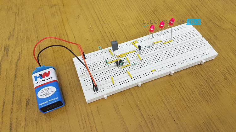
555 PWM LED Dimmer Circuit The circuit uses 12 white LEDs which are super bright. If you choose to attach further LEDs only connect each of the three LEDs as shown in the circuit diagram with a 68-ohm resistor. Applications and Uses. 555 PWM LED Dimmer circuit is used in street lights, lamps, etc.
LED Lamp Dimmer Project Circuit Diagram and Working
LED Lamp Dimmer Circuit - Electronic Circuit LED Lamp Dimmer Circuit. By Electronic Circuit Sunday, May 06, 2012. It does not appear the light stimulation of the human eye when the lights suddenly illuminated , and also can reduce the damage when open lamp impact current to the bulb, circuit is shown in the diagram.

Electrical & Electronics Engineering - LED strip Dimmer ...
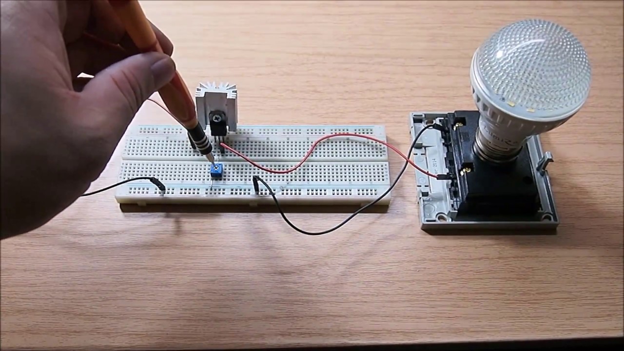
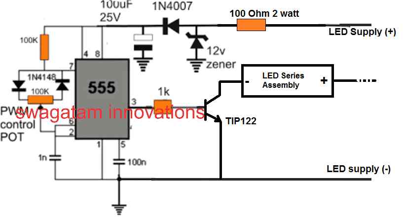
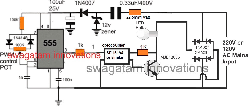
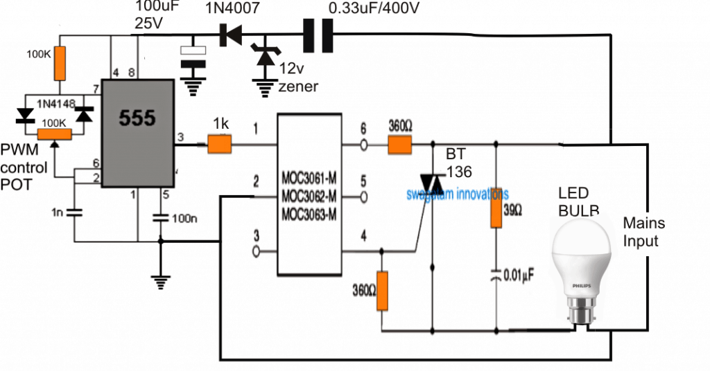
How to Add a Dimmer Facility to a LED Bulb - Homemade Circuit... If used then the LED bulbs do not dim correctly rather show erratic dimming or brightening behavior, due to an incompatible reaction. The connected LED bulb now responds to the PWM content applied by the 555 circuit and proportionately adjusts its brightness as per the user preference.

12V Light Dimmer Circuit
Simple Lamp Dimmer/ Fan Regulator Circuit using a Triac The light dimmer circuit or fan regulator circuit (either case, the circuit, and design are the same, the only difference is the output load to be varied, that is, fan This is the circuit diagram of the simplest lamp dimmer or fan regulator. The circuit is based on the principle of power control using a Triac.
The simplest led dimmer circuit diagram
› what-is-an-emergency-lightEmergency Light : Circuit Diagram, Working and Its Applications Connect the circuit on the breadboard as per the diagram shown below using the above components. In this circuit, the LDR based light will activate a high watt white LED once there is dark in the room. It can be used as a simple lamp in the children’s room to keep away from the panic condition once the power gets fail. This circuit gives ...

5V LED Dimmer Circuit
The simplest led dimmer circuit diagram - YouTube This easy electronic project is the simplest led dimmer that works well and uses minimum electronic components as possible the circuit consumes very low...

LED Dimmer Circuit Using LM317 Voltage Regulator IC
Dimmer circuit using SCR - TRIAC - ElecCircuit.com This is an automatic light dimmer circuit. You do not need to dim the lights by yourself. It is so very convenient because we use the LDR to detect Automatic led night light switch. 555 PWM LED dimmer circuit diagram | Power Battery Saving. Solid State Relay circuit. Get update via email.
Highly Efficient 0-100% LED Dimmer
5V LED Dimmer Circuit - ElectroSchematics.com This is a very simple LED dimmer circuit which has 2 transistors, 1 resistor and 2 potentiometers. Typical segment displays LEDs consume around If a six digit display is to be current limited, at least 42 series resistors are needed. To counter the above described problems, this led dimmer project...

Schematic diagram of LED dimming module. | Download ...
› blinking-led-using-555-timer-icMaking Of Flashing/Blinking LED Circuit Diagram using 555 ... This circuit is designed using a low power consumption output device, a red LED. There are many applications of 555 timers, generally used in Lamp Dimmer, Wiper Speed control, Timer Switch, Variable duty cycle fixed frequency oscillator, PWM Modulation etc.
How to Add a Dimmer Facility to a LED Bulb - Homemade Circuit ...
LED Dimmer with circuit diagram LED Lamp Dimmer Circuit Diagram - ElectronicsHub.Org. For the driving of the LED transistor T1 is used in the circuit as a signal amplifier and to protect the LED from the damage due to high current resistor R6 is employed in the circuit as a current limiter.

Adding a Dimmer to a Power LED Driver : 4 Steps (with ...
Strip LED Dimmer Circuit with IRFZ44N MOSFET LED Strip Dimmer Circuit Diagram part 9. Introduction: Today in this article we are going to discuss the dc LED dimmer with IRFZ44N MOSFET. We are using very minimal components in the Circuit Diagram. Just an IRFZ44N N-Channel Mosfet and a Potentiometer.
LED Lamp Dimmer Project Circuit Diagram and Working
Led Dimmer Circuit Diagram Luxury Soldering Iron Temperature... It is also called PWM LED dimmer circuit diagram. By changing the pulse width of square wave, it is possible to control the brightness of LED. We have already discussed about the PWM signal generation before.
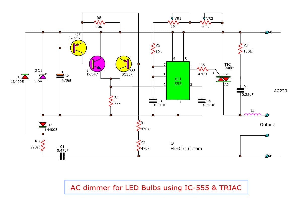
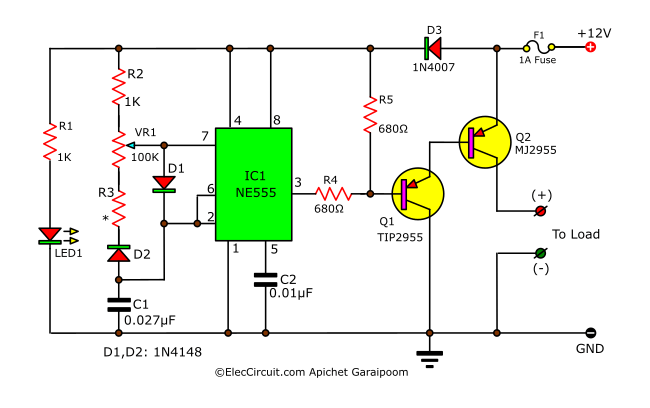
AC dimmer for LED Bulbs using IC-555 & TRIAC | ElecCircuit.com
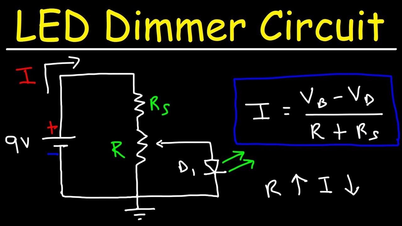
LED Dimmer Circuit | REUK.co.uk This dimmer circuit cannot be used to turn the LEDs all the way off or to full brightness. In fact it operates within a duty cycle range of 5%-95 While individual LED bulbs are completely unharmed by being turned on and off rapidly, the internal circuitry of the spotlight unit does not appear to like it at all.

Power LED Dimmer Circuit – Electronics Projects Circuits
PDF LED Lamp Dimmer Circuit | Circuit Diagram of LED Lamp Dimmer In this circuit, at the starting LED glow slowly, then grown brighter and once again slowly it became dim. The basis of the whole circuit is an operational amplifier IC named LM358. Circuit Diagram of LED Lamp Dimmer

Dimmer With A MOSFET | Diagrama de circuito, Circuito ...
circuitdigest.com › electronic-circuits › 12v-dual+12V and -12V Dual Power Supply Circuit Diagram Oct 06, 2017 · Circuit Diagram: Constructing Dual Power Supply Circuit: Step-I: Converting 220v AC into 12v AC using Step Down Transformer. The primary terminals of the centre tapped transformer is connected with household supply (220V ac, 50Hz) and output is taken from secondary terminals of the transformer. The centre tapped describes the voltage output of ...
Highly Efficient 0-100% LED Dimmer
LED Dimmer Circuit - Lighting | Led dimmer, Electronics circuit... PWM based LED Dimmer Using 555 - Circuit, Block Diagram, Working. Read this post to get knowledge about circuit diagram and working of PWM LED Dimmer Using 555 Timer IC. Here, we use PWM Technique to dim the intensity of light of the LED using 555 Timer IC.

Simple & Easy Dimmer Circuit Using 555 IC for LED Strip ...
Fan Regulator Circuit, AC Lamp Dimmer, Ceiling Fan Electronic... This is 220v ac dimmer circuit diagram based on capacitor, in the capacitive Dimmer/regulator no noise.Resistor, One Capacitor, One Diac And One Triac. TRIAC is a semiconductor device belonging to the family of thyristors.

Electrical – FL5150 (LED dimmer) circuit explanation – iTecTec
220V AC Light/Fan Dimmer using TRIAC & Arduino Here is a circuit diagram for 220V AC Light Dimmer/Fan Speed Controller using TRIAC & Arduino. The schematic has been designed using EasyEDA online PCB Designing tool. After that you can solder all the necessary components as per circuit diagram and make the final product ready.

Simple LED Dimmer with Potentiometer
البشع تحمل مزيج led lamp dimmer circuit - hrmedianet.com

Led Strip Dimmer | Led Dimmer | DC Voltage Regulator | Led ...

Pin on Electrónica
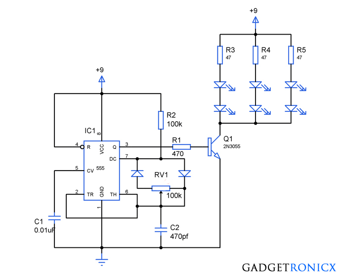
PWM LED dimmer circuit using IC 555 - Gadgetronicx

LED Dimmer circuit using 555 timer IC

3V LED Dimmer Circuit - Hackster.io
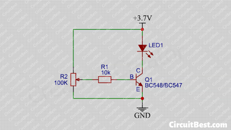
3V LED Dimmer Circuit with BC547 Transistor - CircuitBest
30mA LED Dimmer Circuit Diagram
How to Add a Dimmer Facility to a LED Bulb - Homemade Circuit ...

LED strip dimmer circuit using 555 ic | PWM LED dimmer

LED-Lamp-Dimmer-Circuit-Diagram | Circuit diagram, Led lamp ...

The simplest 12 volts led dimmer circuit diagram
Simple LED dimmer circuits
LED Dimmer Circuit - Brightness Control Using a Potentiometer

Simple 12V Lamp Dimmer | Circuit Diagram

12V LED Dimmer Circuit

LED Dimmer Circuit | Circuit Diagram

110V/230V Light Dimmer Circuit without Snap-on

LED dimmer circuit | Electronics Forums
555 PWM LED dimmer circuit diagram | Power Battery Saving ...


Comments
Post a Comment