39 ansul microswitch wiring diagram
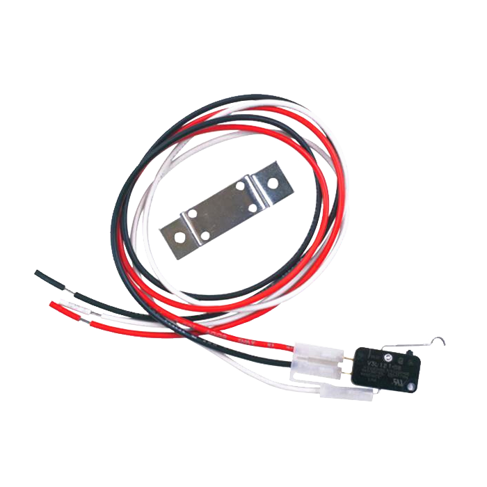
PDF Electrical Control Panel Wiring Instructions 4. Wire fromT1, T2, T3 on each Starter(s) to each three phase motor. See label below thermal over- load. 5. Wire from T1, T2, T3, 14 on each Contactor to each single phase motor. See label below Starter Contactor. 6. Fire System Micro Switch from the ANSUL or PYROCHEM Fire Suppression System connect wires How to wire a ansul r102 - JustAnswer no.I need only to wire the ansul,the fan an the three light of the hood to the bracker panel. The ansul have 6 wire 2 brown 2 black 2 red. Jason : OK, some fire inspectors say the hood lights have to turn off when a pull station is activated. Others say the lights can stay on. Do you know how you plan to address the hood lights?
Fire System Microswitch Wiring - YouTube CASService explains how to wire the exhaust hood fire system microswitch to an exhaust hood control package. For questions, please contact CASService at 1-86...

Ansul microswitch wiring diagram
How to wire an Ansul system switch; has a common, NO and a ... Next, route a black or red wire from a single pole 120 volt breaker to the common wire in the Ansul micro switch box. Next, route a black or red wire from the N.O. on the same set of contacts back to the other shunt trip lead. When the Ansul system is activated, the N.O. contacts will close, and the shunt trip leads will see 120 volts, trip the ... PDF Ansul Kitchen Hood Suppression Wiring Diagram wiring diagram siredward co. ansul micro switches wiring diagram 2 ansul wiring. ansul kitchen hood suppression wiring diagram mehrpc de. ansul r102 owners manual firefighting duct flow. fire suppression system wiring diagram imageresizertool PDF Ansul Micro Switch Wiring Diagram - speedo.co.uk Ansul Micro Switch. Switch Wiring Diagram Ansul System Micro Switch Wiring. How To Wire An Ansul System Switch Has A Common NO And A Fire Suppression System Micro Switch Electrical April 14th, 2019 - Fire suppression systems many times need to do more than just shut down the MAU They
Ansul microswitch wiring diagram. Wiring Diagram For Shunt Breaker In Fire Suppression System This diagram can help clear up the wiring in of fire alarm modules and relays. using an addressable relay module (FRM-1) to operate the shunt trip breaker directly. Labels: elevator equipment, elevator machine room, elevator recall, Waterflow, Backflow, PIV and OS&Y · Sprinkler Waterflow Flapper. Ansul System Wiring Diagram - Wiring Diagram September 14, 2021 · Wiring Diagram ansul system wiring diagram - You will need a comprehensive, skilled, and easy to understand Wiring Diagram. With this kind of an illustrative guide, you'll be able to troubleshoot, avoid, and complete your projects with ease. Ansul system micro switch wiring diagram" Keyword Found ... Wiring Diagram For Shunt Breaker In Fire Suppression System. Diagramweb.net DA: 14 PA: 50 MOZ Rank: 80. Run a low voltage wire from the 12v micro switch in the ansul system to the 12v shunt trips.(Shunt trips come in several voltages) Make sure that the make up air shuts off ; In these cases, a shunt-trip breaker is installed in the circuit feeding the elevator controls, and the fire alarm ... Ansul Wiring Diagram - schematron.org How to wire an Ansul system switch; has a common, NO and a NC Next, route a black or red wire from a single pole volt breaker to the common wire in the Ansul micro switch box. Please help the wiring diagram.
Ansul Home Authorized ANSUL Distributors offer the highest caliber of quality products, service and support worldwide. ANSUL® Non-Fluorinated 3x3 UL201 foam concentrate sets the new standard for Class B firefighting. The ANSUL® Lithium-Ion Risk Prevention System offers advanced early failure monitoring of Lithium-Ion batteries by detecting off-gases. Cool Water Cooler Circuit Diagram Ansul System Micro ... Using the diagram below describe the water cooling sytem first in writing then make an oral presentation of the same. Founded in 1950 pittsburgh water cooler located in glenshaw pa has been the leader in supplying water coolers drinking fountains repair parts and expertise to the drinking water industry for over 60 years. Ansul Operation, Mechanical Recharge, Manual operable. The Ansul-authorized distributor should stress the importance of performing these inspections at regularly scheduled intervals. 2. Maintenance is a vital step in ensuring the reliability of a MICRO-K System and must be performed by the Ansul-authorized distributor. 3. NFPA and Ansul suggest (as a minimum) six month main-tenance intervals. PDF Engineering Specifications - Ansul ANSUL SAPPHIRE Clean Agent Fire Suppression System 2 with AUTOPULSE Z-10 Conventional Detection System B. The standards listed, as well as all other applicable codes, standards, and good engineering practices, shall be used as "minimum" design standards.
Ansul R 102 Wiring Diagram Ansul R 102 Wiring Diagram This manual is intended for use with ANSUL® R Restaurant. Fire Suppression Systems. Those who install, operate, recharge, or maintain. ANSUL. DESIGN INSTALLATION RECHARGE AND MAINTENANCE MANUAL. R RESTAURANT FIRE SUPPRESSION SYSTEM (Standard UL Listed). Label System (Wiring Diagram) Remote Release R Ansul. Ansul System wiring - Electrician Talk It likely has a contactor, and the microswitch controls the coil. There could be a fuse in the hood, that opens in case of fire, mechanically operating the microswitch. There is usually a wiring diagram with the unit. The range hood installer will tell you what is required. At least he should! The gas valve has a solenoid. PDF R-102 Restaurant Fire Suppression System This manual is intended for use with ANSUL®R-102 Restaurant Fire Suppression Systems. Those who install, operate, recharge, or maintain these fire sup- pression systems should read this entire manual. Specific sec- tions will be of particular interest depending upon one's responsibilities. PDF R-102 RESTAURANT FIRE SUPPRESSION SYSTEM - CaptiveAire 2014-SEP-01 REV. 11 R-102 Restaurant Fire Suppression Manual This manual is intended for use with ANSUL®R-102 Restaurant Fire Suppression Systems. Those who install, operate, recharge, or maintain these fire suppression systems should read this entire manual. Specific sections will be of particular interest depending upon one's
Need help to wire ansul system with 2 micro switch. When ...
Ansul Wiring Diagram Product Code. phase from control panel to fans (see wiring diagram.) - *1 or 3 Two Ansul micro switches are wired to control panel from fire system. Input power of . A new ansul system has been installed. The new system has two operating the microswitch. There is usually a wiring diagram with the unit.P ermit D rawings.
Installation, Operation, and Maintenance Manual
Ansul System Drawings [AC4FL8] Ansul System Wiring Diagram - ansul fire suppression system wiring diagram, ansul system micro switch wiring diagram, ansul system wiring diagram, Every …. suppression system as specified herewithin and as shown on the design drawings. Brands: Ansul. by admin Dec 27, 2016. Fire suppression systems are mechanical devices.

I have the need to operate an ansul system using contactors ...
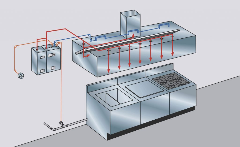
Superior Hoods MICROSWITCH Micro Switch for Fire ... Adding a Micro Switch to your Fire Suppression System's control box will ensure: If your system is triggered, the Make Up Air fan's power will be cut off so as not to feed the fire with fresh air. Your Exhaust fan will continue running to remove smoke and fumes from the fire, out of the kitchen. Attention CA Residents Manufacturer Information
Ansul R102 Fire System Drawing
How to correctly wire an ANSUL system - YouTube What needs to connect to what and how to do it.
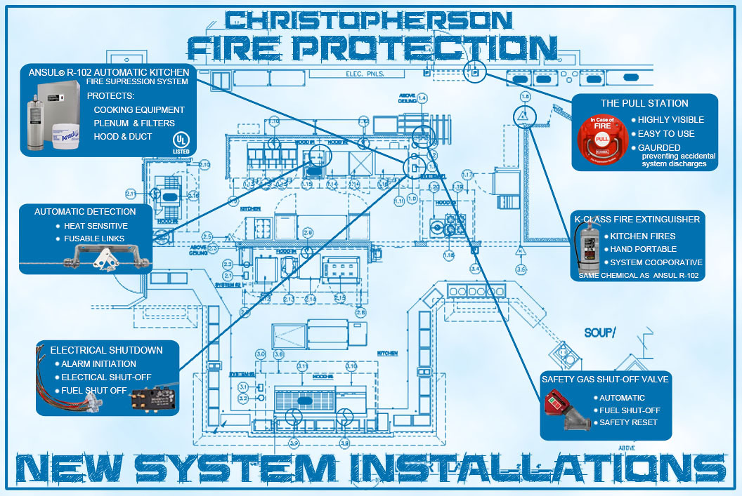
Commercial Kitchen Hood Systems – ANSUL Distributor
Ansul System Electrical Wiring Diagram - Wiring Diagram Critique My Diagram Mike Holt S Forum. Ansul r102 fire system drawing hood schematic commercial kitchen vent wiring contractor talk electrician air to be shut off when the check snap action switches into switch using contactors large 15f pre packaged interlock knight ii general information heiser oem components protex critique my diagram page 2 mike electric gas valve and manual reset relay ...

DC POWER SYSTEM WIRING DIAGRAM (Continued) - TM-55-1520-240-T ...
Wire from shunt trip breaker to ansul system | Mike Holt's ... gadfly56. Usually just stay with the size of wire the control circuit breaker dictates, 15 amp, #14, 20 amp #12. The fire suppression contact is usually rated for only 3-5 amps, some may be more depending on the manufacture. As Larry said, some shuntrip breakers are not rated for constant voltage, but most are.
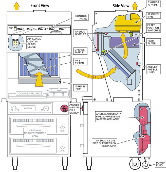
Universal Ventless Hood, 26 inch Model # WVU-26
Ansul Shunt Trip Wiring Diagram - schematron.org Two Ansul micro switches are wired to control panel from fire system.Jul 27, · Have ansul system activate the shunt trip. Feed make up (supply) air,all electrical equipment and outlets, except for exhaust fan located under the hood through sub panel. , PM The suppression tech will also have the wiring diagram.
Heiser > OEM System Components > Range Guard and Kidde WHDR ...
Ansul-style - Microswitches - Restaurant System Parts ... Ansul 423880 R 102 System Parts - 3PDT Electric Switch. Manufacturer: Ansul Ships From: FL. 3PDT Switch (Electrical) for Ansul Restaurant Systems. Price: $97.19. Part #: Ansul 423881.
Range-Guard Style SPDT Microswitch, UL Classified : Steel ...
PDF Ansul Micro Switch Wiring Diagram - speedo.co.uk Ansul Micro Switch. Switch Wiring Diagram Ansul System Micro Switch Wiring. How To Wire An Ansul System Switch Has A Common NO And A Fire Suppression System Micro Switch Electrical April 14th, 2019 - Fire suppression systems many times need to do more than just shut down the MAU They

KITCHEN SUPPRESSION SYSTEM – System and Solution
PDF Ansul Kitchen Hood Suppression Wiring Diagram wiring diagram siredward co. ansul micro switches wiring diagram 2 ansul wiring. ansul kitchen hood suppression wiring diagram mehrpc de. ansul r102 owners manual firefighting duct flow. fire suppression system wiring diagram imageresizertool
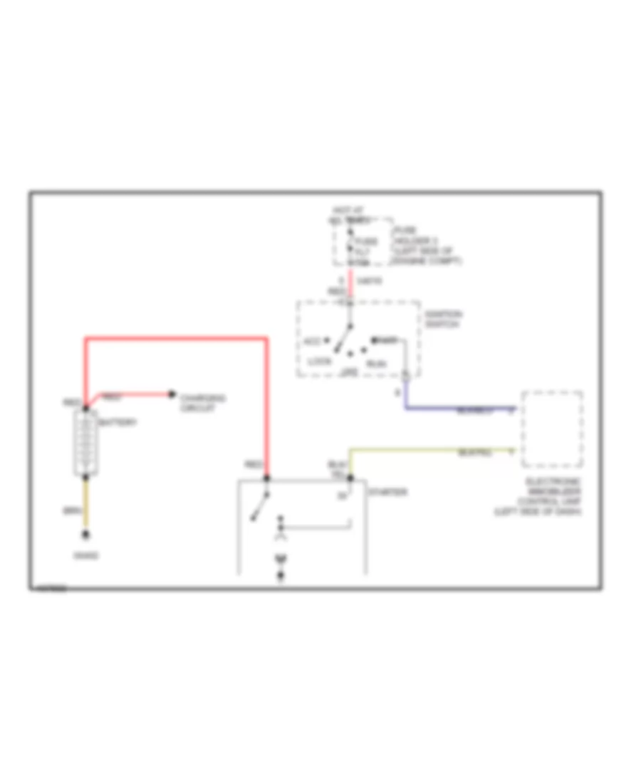
STARTING/CHARGING – MINI Cooper 2005 – SYSTEM WIRING DIAGRAMS ...
How to wire an Ansul system switch; has a common, NO and a ... Next, route a black or red wire from a single pole 120 volt breaker to the common wire in the Ansul micro switch box. Next, route a black or red wire from the N.O. on the same set of contacts back to the other shunt trip lead. When the Ansul system is activated, the N.O. contacts will close, and the shunt trip leads will see 120 volts, trip the ...
Ansul R102 Fire System Drawing
R-102 RESTAURANT FIRE SUPPRESSION SYSTEM

Small — 5F Pre-Packaged Fire Suppression System
Ansul wiring check | Electrician Talk
Commercial Hood Electrical Wiring | Electrician Talk

How to wire a ansul kitchen hood system
Ansul Pre-Pipe Fire System 5' (Concession Only)
ansul wiring | Electrician Talk

Projects in Progress: Caterpillar Dealer Relies on Fire ...

I need a wiring diagram for a commercial kitchen vent hood
Submittal Drawing
PIRANHA Restaurant Fire Suppression Systems

Field wiring for the ansul snap-action switch, Ansul wiring ...

Ansul-Style DPDT Microswitch: Electronic Component Limit ...

Ansul system | Mike Holt's Forum
R-102 Intro Rev Record

Kitchen Hood Fire Suppression System Installation | Kitchen ...
AMERICAN HOOD SYSTEMS, INC

Fire Suppression Systems for Commercial Kitchens – Streivor ...

I am wiring an ANSUL fire suppression system and need to know ...
Z-20 Fire Control Panels
EXAMPLE DRAWINGS PROVIDED BY: http://www.firesystemdrawings ...

ANSUL Fire Suppression Systems Installation Inspection ...

Critique my diagram. | Mike Holt's Forum
ANSUL system interlock? | Electrician Talk
Heiser > OEM System Components > Protex II System Components ...
Electric Gas Valve and Manual Reset Relay

Ansul 426151 Relay - Manual Reset - 120V, 60 Hz


Comments
Post a Comment