40 accelerator pedal position sensor wiring diagram
2013 Maxxforce 13 Throttle Pedal Wiring Diagram APS/IVS Accelerator position signal in range DTC APS/IVS Install the 5 wire breakout tee between the APS/IVS sensor and harness. The idle validation switch attaches to the accelerator pedal or hand control as a separate 5 is a schematic diagram of the sensor and electronic fuel control system .. PDF IK0800219 - Accelerator Position Sensor/IdleValidation ... mounted on the accelerator pedal. The accelerator pedal assembly is serviceable to the extent that the APS/IVS switch can be replaced without replacing the complete assembly. Accelerator Position Sensor (APS) The ECM sends a regulated 5V signal through the ECM black chassis connector terminal 3 to APS connector terminal C.
Accelerator Pedal Assembly Toyota Camry Accelerator Pedal Position (APP) Sensor Harness. Toyota Camry. APP Sensor Harness. Note: 6 wires used for Two Position. Sensors. Position Sensor Circuit.6 pages
Accelerator pedal position sensor wiring diagram
Accelerator Pedal Position Sensor Circuit Diagram ... January 29, 2022 · Wiring Diagram accelerator pedal position sensor wiring diagram - You will need a comprehensive, skilled, and easy to understand Wiring Diagram. With such an illustrative guidebook, you'll be able to troubleshoot, prevent, and full your assignments with ease. Not only will it help you accomplish your desired… Nissan accelerator pedal position (APP) sensor - Erwin Salarda OPERATION PROCEDURE 1. Make sure that accelerator pedal is fully released. 2. Turn ignition switch ON and wait at least 2 seconds. 3. Turn ignition switch OFF and wait at least 10 seconds. 4. Turn ignition switch ON and wait at least 2 seconds. 5. Turn ignition switch OFF and wait at least 10 seconds. LIST OF DTC P2138 P2138 Code: Throttle/Pedal Position Sensor/Switch D/E ... The P2138 trouble code is triggered when there are problems with the throttle/pedal position sensor/switch. However, it's not the only code related to the throttle body and its circuitry. The P2135, P2136, P2137, P2139, and P2140 DTCs also indicate issues in the same areas.
Accelerator pedal position sensor wiring diagram. Accelerator Pedal Position Sensor Wiring Diagram ... Accelerator Pedal Position Sensor Wiring Diagram - wiring diagram is a simplified satisfactory pictorial representation of an electrical circuit. It shows the components of the circuit as simplified shapes, and the skill and signal links amongst the devices. Accelerator Pedal Position Sensor, 6 Pin Wiring Diagram ... So, a 6 pin accelerator pedal position sensor wiring diagram is, two wires are for the earth, two for the input voltage, and two for signals back to the computer (ECU). Non-Contact Type Accelerator Pedal Position Sensor (APPS) The non-contact-type accelerator pedal position sensor is of hall effect and inductive type. How To Test The GM Accelerator Pedal Position (APP) Sensor 1 That the Accelerator Pedal Assembly is made up of 3 individual position sensors. Each one has separate signal, Ground, and 5.0 volt reference circuits. That APP Sensor 1's signal increases as the accelerator pedal is depressed, from below 1.1 volt at 0% pedal travel (pedal at rest) to above 2.1 Volts at 100% pedal travel (pedal fully depressed). How to Test a Throttle Position Sensor TPS - Without a ... Here is a quick video on how to test a Throttle Position Sensor TPS with a multimeter. Also I show you how you can figure out what each wire on your sensor i...
DTC P2122/104 THROTTLE/PEDAL POSITION SENSOR ... WIRING DIAGRAM INSPECTION PROCEDURE 1 READ VALUE OF HAND-HELD TESTER(ACCEL POS #1 AND #2) (a) Connect the hand-held tester to the DLC3. (b) Turn the power switch ON (IG). (c) Turn the hand-held tester ON. (d) On the hand-held tester, enter the following menus: DIAGNOSIS / ENHANCED OBD II / HV ECU / DATA LIST. Accelerator pedal | Tacoma World Troubleshooting the pedal position sensor is gonna be difficult. omgwtfbbq!, Apr 10, 2018 #6. Apr 10, 2018 at 12:18 PM ... I would download the schematics/block diagrams for the accelerator sensor circuits and start testing. ... it's possible you did something to a wire or have a bad ground (did you disconnect your battery or anything in the ... 2013 Maxxforce 13 Throttle Pedal Wiring Diagram 2013 Maxxforce 13 Throttle Pedal Wiring Diagram MAXXFORCE 11 and 13 Beginning with Model Year R section of Engine Diagnostics Manual EGES before doing any diagnostic procedures. . 2 Engine Throttle Control Engine Throttle Position Engine Throttle Valve Fuel Delivery. A. F. +. R4. MaxxForce DT, 9, 10 ( - ). Engine Wiring Diagram CAN-L (GN). wire diagram..peterbilt side of the throttle position ... I need the wire diagram for the peterbilt side of the throttle position sensor. The unit had a brake in the original oem harness to the ecm. A pete dealer by passed the harness and went straight to the ecm. In doing so they removed the pins from the 3 pin connector on the floor. Wire colors a red with org trace, blue and black with white trace.
6 Signs Of A Bad Accelerator Pedal Sensor (Replacement Cost) Accelerator Pedal Position Sensor Replacement Cost The average accelerator pedal sensor replacement cost is between $100 and $300, depending on the car model and labor costs. The accelerator pedal sensor usually costs between $50 and $200. The labor cost can range from $50 to $100 at a workshop. PDF Accelerator Position Sensor/Idle Validation Switch APS ... • 0 V when the pedal is at the idle position. Ł B+ when the pedal is depressed The IVS receives a 12 V ignition voltage at Pin F from the ignition fuse in the power distribution box. When the pedal is not in the idle position (throttle applied), the IVS supplies a 12 V signal to the ECM. T100 Throttle Position Sensor Wiring Diagram Disconnect the wiring connectors from the fuel injectors and the throttle position sensor. 1. Injector connector 2. Throttle position sensor connector Release the retaining clips securing the airbox rubbers to the throttle bodies. Slacken the retaining clips securing the intake rubbers to the throttle bodies and cylinder head. Wiring diagram for accelerator pedal to ECU | Page 2 ... The cranks sensor should be a 2 pin inductive sensor that generates a voltage when the engine spins. The cam sensor is a hall effect sensor and will have a voltage from the ecu @ 5v like you say. If you are measuring 2.3v, on a 3 wire sensors supply wire then there is either a wiring fault or an ecu fault. Check power at the ecu side to confirm ...
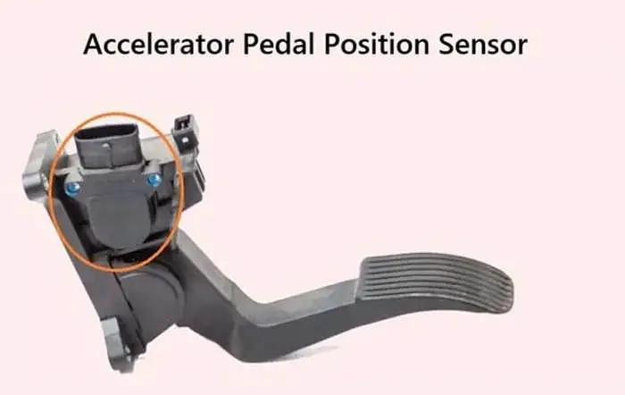
Accelerator Pedal Position Sensor, 6 Pin Wiring Diagram, & Types
Repair Guides | Automatic Transmission (2004) | Dtc P1705 ... accelerator pedal position sensor wiring diagram - You will want a comprehensive, expert, and easy to know Wiring Diagram. With this sort of an illustrative manual, you are going to be able to troubleshoot, avoid, and total your tasks with ease.

GM Gen III LS PCM/ECM: Electronic Throttle Equipment Guide
Accelerator Pedal Position Sensor | The Diesel Stop If you had cut wires it is likely you mis-matched a couple wires. The Accelerator Pedal Position sensor has two potentiometers that act to validate pedal position. But if there is a problem with one sensor the pedal should still work but you will have warning indicators on. If both are malfunctioning nothing will happen with the pedal.
Kia Amanti Questions - Can anyone tell show me the wiring ...
P2138 -accelerator Pedal Position Sensor 1/2 Correlation For a complete THROTTLE CONTROL SYSTEM wiring diagram, refer to the appropriate W iring Information . THEORY OF OPERATION Accelerator Pedal Position (APP) Sensor applications today use Induction/Hall Sensors (non-contact). The Electronic Throttle Control (ETC) system uses two Accelerator Pedal Position (APP) Sensors to
Accelerator pedal position (APP) sensor wiring diagram ...
Accelerator Pedal Position Sensor - How To Diagnose And ... 6 Pin Accelerator Pedal Position Sensor Wiring Diagram As we covered the basics of the accelerator pedal position sensor and learned what this sensor does behind the curtain. We can now focus more on the technical aspect of this sensor. Namely, the 6-pin accelerator pedal position sensor wiring diagram. How this sensor is wired?
Throttle position sensor wiring | GMC Terrain, Equinox, and ...
PDF Golf Throttle Position Sensor Wiring Diagram harness amp throttle position sensor, throttle position sensor wiring diagram 1997 1998 ford 4, p2138 dtc throttle pedal pos sensor switch d e voltage, where is the tps sensor located or a diagram of it on a, 2000 golf throttle position sensor wiring diagram pdf download, throttle pedal position sensor help please tdiclub forums, throttle ...

Failsafe of Accelerator Pedal Position Sensor - Toyota Camry ...
App Sensor Wiring Diagram - Wiring Diagram and Schematics Part 1 How To Test The Gm Accelerator Pedal Position App Sensor Tac System Wiring Diagram 2006 2007 4 2l Chevrolet Trailblazer Dtc P2128 00 Pcm Skyactiv G 2 0 2016 Nd Manual Gm Gen Iii Ls Pcm Ecm Electronic Throttle Equipment Guide Pulling Codes Troubleshooting Honda Cr V Dtc P2122

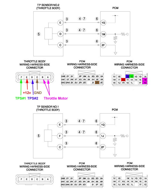
Throttle Body wiring diagram - Engine Maintenance and ...
Throttle Position Sensor Problems - Solving them. Joined: Jun 2016. RE: Throttle Position Sensor Problems - Solving them. I was taught that all wire repairs should be soldered with a linesman's knot and heat shrinked at a minimum, with adhesive heat shrink used on exterior connections. Butt connectors should be used just to get you from point A to B for a proper repair.
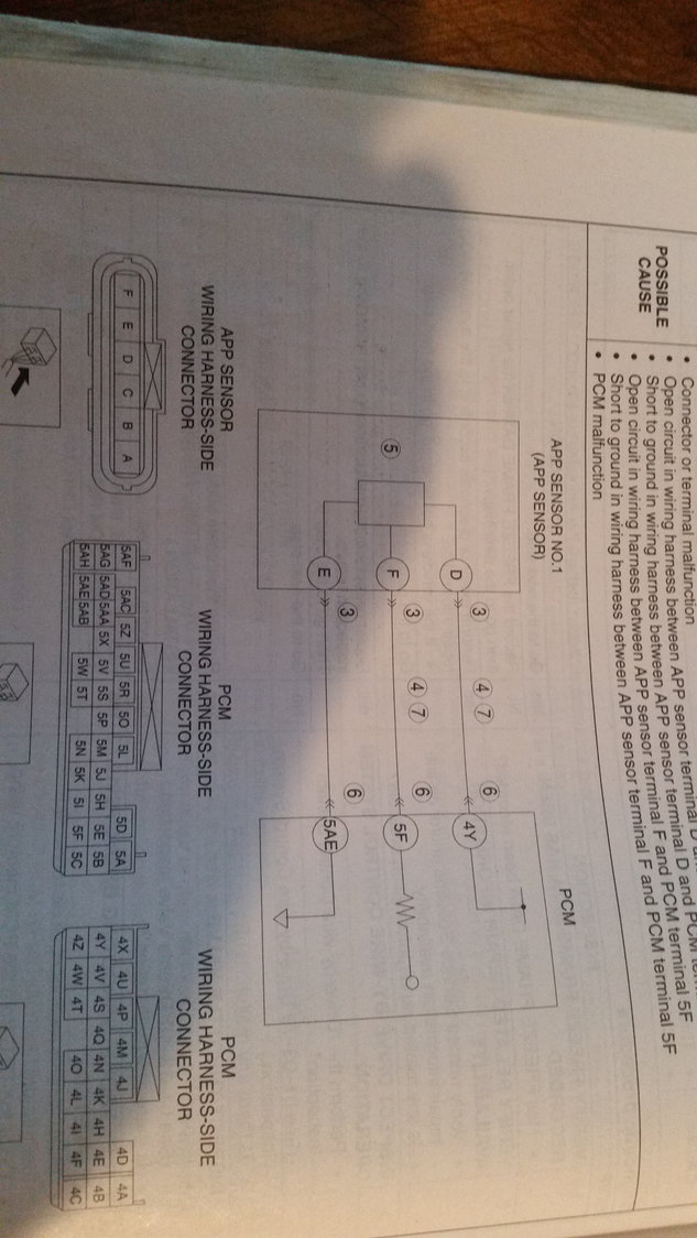
CIRCUIT DIAGRAM
Accelerator pedal sensor wiring | Ford Powerstroke Diesel ... The wiring harness for the tuner that is supposed to plug into accelerator sensor is a 10 wire single head and the accelerator on the Exc is a dual head accelerator with two smaller heads and only 5 wires combined. I can see where there are other loose cut wires coming out of the dash in the harness.

Pic Request: Throttle Position Sensor Connector Wiring ...
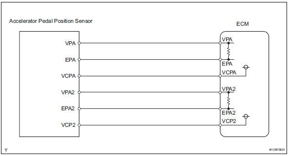
Accelerator pedal position sensor - analog Waveform notes. In this example, the Accelerator Pedal Position (APP) sensor is of the potentiometer type. It receives two reference voltages from the Powertrain Control Module (PCM), having two ground wires and two signal wires that send a varying voltage back to the PCM relating to accelerator pedal position.
Drive By Wire Throttle Wiring Question - RX8Club.com
Throttle Body (TAC) Circuit Wiring Diagram (2007-2008 3.5L ... DIAGRAM 2: Accelerator Pedal Position (APP) Sensor Circuits. More 3.5L V6 Chevy Malibu Tutorials . If you need to test the electronic throttle body itself, check out this tutorial: Electronic Throttle Body Tests (2007-2009 3.5L Chevrolet Malibu And Pontiac G6) .
Toyota RAV4 Service Manual: Throttle / pedal position sensor ...
Accelerator Pedal Position Sensor Archives - Easy Car ... On this page, you are going to quickly learn the seven bad accelerator pedal position sensor symptoms in less than 2 minutes. The A-Z Of Accelerator Pedal Position Sensor, 6 Pin Wiring Diagram, & Types Leave a Comment / Accelerator Pedal Position Sensor / By IQBAL KHAN
GSIC - Global Service Information Center
P2138 Code: Throttle/Pedal Position Sensor/Switch D/E ... The P2138 trouble code is triggered when there are problems with the throttle/pedal position sensor/switch. However, it's not the only code related to the throttle body and its circuitry. The P2135, P2136, P2137, P2139, and P2140 DTCs also indicate issues in the same areas.

please help with wiring my TPS (position of each wire) | Kia ...
Nissan accelerator pedal position (APP) sensor - Erwin Salarda OPERATION PROCEDURE 1. Make sure that accelerator pedal is fully released. 2. Turn ignition switch ON and wait at least 2 seconds. 3. Turn ignition switch OFF and wait at least 10 seconds. 4. Turn ignition switch ON and wait at least 2 seconds. 5. Turn ignition switch OFF and wait at least 10 seconds. LIST OF DTC P2138
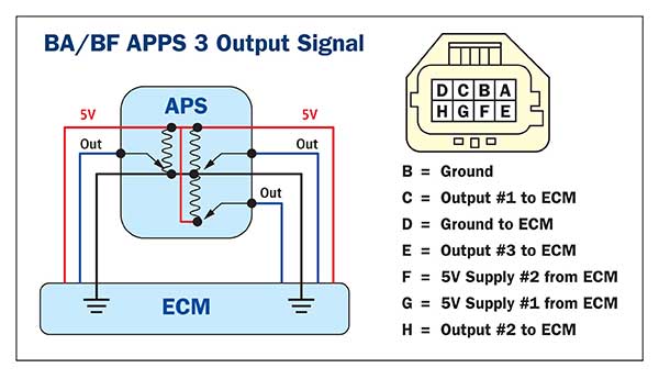
Accelerator Pedal Position Sensors (APPS)
Accelerator Pedal Position Sensor Circuit Diagram ... January 29, 2022 · Wiring Diagram accelerator pedal position sensor wiring diagram - You will need a comprehensive, skilled, and easy to understand Wiring Diagram. With such an illustrative guidebook, you'll be able to troubleshoot, prevent, and full your assignments with ease. Not only will it help you accomplish your desired…

Automotives HuB - App sensor wiring diagram | Facebook

Throttle Body Wiring | Toyota Nation Forum
2014 Tundra SR5 Throttle position sensor wiring diagram ...

7 4 wheelers ideas | motorcycle wiring, electrical wiring ...
Drive By Wire Throttle Wiring
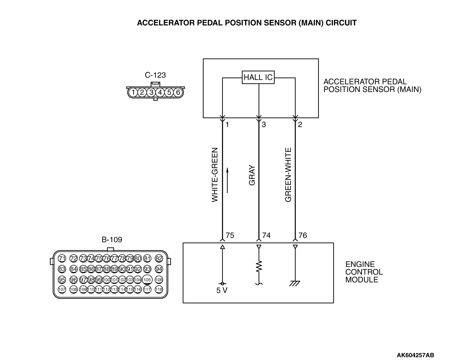
13B-DTC P2122: Accelerator Pedal Position Sensor (Main ...
Fly by wire pin out diagram | Just Commodores

Throttle body wiring | Jeep Patriot Forums
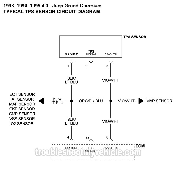
1993-1995 TPS Wiring Diagram (Jeep Grand Cherokee 4.0L)

Accelerator pedal position sensor wiring diagram working ...

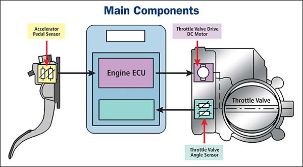
Throttle position control system | Download Scientific Diagram
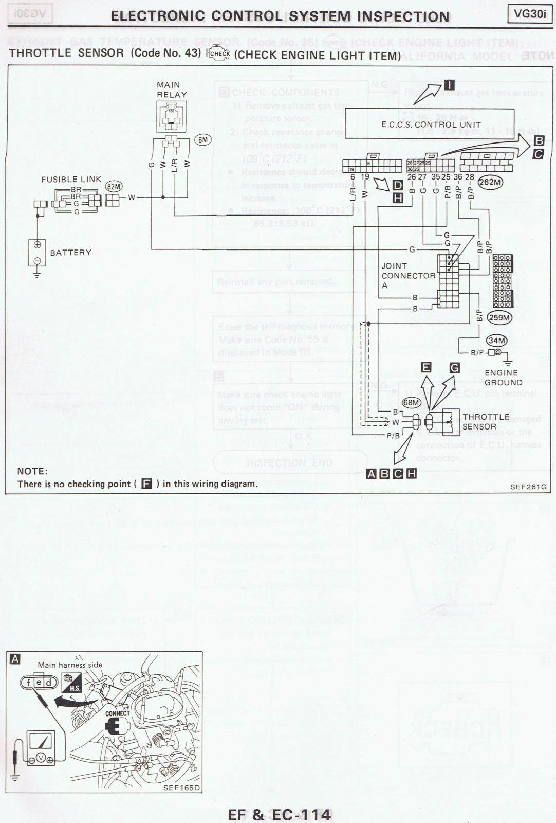
87 Pathfinder TPS wiring diagram - 86.5-89 WD21 Pathfinders ...

FOR THE WIRING DIAGRAM THROTTLE POSITION SENSOR PLUG, IT USE ...
1996-1998 TP Sensor Circuit Diagram (2.0L Neon)
1.8t throttle pedal wiring | Club GTI
DBW Pedal Wiring Questions - LS1TECH - Camaro and Firebird ...
Testing Accelerator Pedal Position Sensors (APS)
Does anyone have accelerator pedal pinout? - RX8Club.com

TechDoc

Wiring diagram of a forklift accelerator pedal circuit ...

GM Gen III LS PCM/ECM: Electronic Throttle Equipment Guide

Chevrolet Throttle Position Sensor Diagnosis and Repair Help ...
Throttle Position Sensor Wiring Diagram (1997, 1998 Ford 4.6L ...

More insight on Nissan 6 wire throttle position sensor How it ...
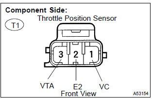
Toyota Corolla Repair Manual: Inspection procedure - Throttle ...

Throttle Position Sensor - Toyota Engine Control Systems


Comments
Post a Comment