41 patchbay wiring diagram
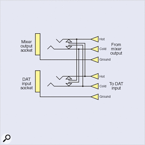
Circuit Schematics Overview (Internal Normals) - Bittree Schematic overview for standard audio patchbays.For full-size view, please click the DOWNLOAD INSTRUCTIONS link located below. Download Instructions. Patchbay Diagram Oct 02, 2019 · A patchbay can make your studio much quicker to use, but can also be a The normalled jack sockets will therefore look like the diagram in Figure 2a.Apr 15, · Patchbay Wiring? It also appears that in your second diagram that the "hot" is wired to the ring of the patchbay. i am, however, assuming that the red line is the "hot".
Studio Wiring And Patch Bays - Everything You Need To Know 7 Mar 2021 — At its most basic, a patchbay brings the connections from the back panels of all your gear (whether that is outboard equipment, like compressors ...

Patchbay wiring diagram
The Basics of Patchbays: Patchbay Basics | Tape Op ... A patchbay is a central audio connection area for all the gear in a studio that allows any connection to or from equipment to be made in one location with a standardized cable and connector. Patchbays not only save time and headaches, they allow you to easily perform a number of mix tricks that would take serious head-scratching otherwise. PATCHBAYS R US - Dancetech I need some basic patchbay wiring diagrams. I am trying to "paper" design a project studio and I need to see schematic's from the mic panels all the way to the outboard gear. I still have no visual help to work with. I was hoping to have this with in the week. If there is anyway you might be able to help me in this search, e-mail me with the ... Patchbay Setup Diagram BUILDING THE PATCHBAY SETUP. This method This is the SIMPLIFIED DIAGRAM used to represent either of the above types of mixers. It will be used in the. I'm thinking of getting a patch bay for my home studio. I'm still barely grasping the specifics of how to make this work. I've drawn up a diagram of. How to use patch bays in your recording studio.
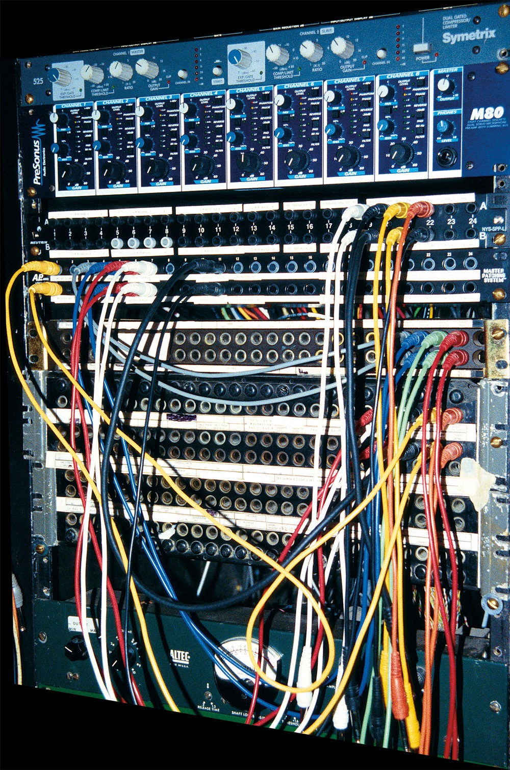
Patchbay wiring diagram. How to Use a Patchbay | LedgerNote You plug in a patch cable and route it to the bottom row, which is the exact opposite of the top row. It is only for inputs on your gear. The signal flows into the cable, into a bottom front jack, and out of the bottom back jack and into an input in another piece of gear. The inputs are bottom only, front-to-back. Patchbay Setup Diagram - Wiring Diagram Pictures A patchbay is a central audio connection area for all the gear in a studio that allows any connection to or from equipment to be made in one location with a standardized cable and connector. Patchbays not only save time and headaches, they allow you to easily perform a number of mix tricks that would take serious head-scratching otherwise. PATCHBAY SETUP DIAGRAM NEEDED !!! - Avid Pro Audio Community patchbay setup diagram needed !!! I have a digi 003 rack , 24 channel patch bay and several pieces of outboard sound modules - Fantom , proteus 2000 , turbo phatt , trinity , virus , motif keyboard and a mpc 4000. Audio Accessories_Pinouts - Patchbays Audio Accessories patchbay pinouts don't necessarily represent other manufacturers. CANNON DL96R (Female) The following is the "Standard Audio Configuration" pinout for CANNON DL 96-Pin connections. We acknowledge the wide variety of pinouts that are in use, and can accomodate any requirement.
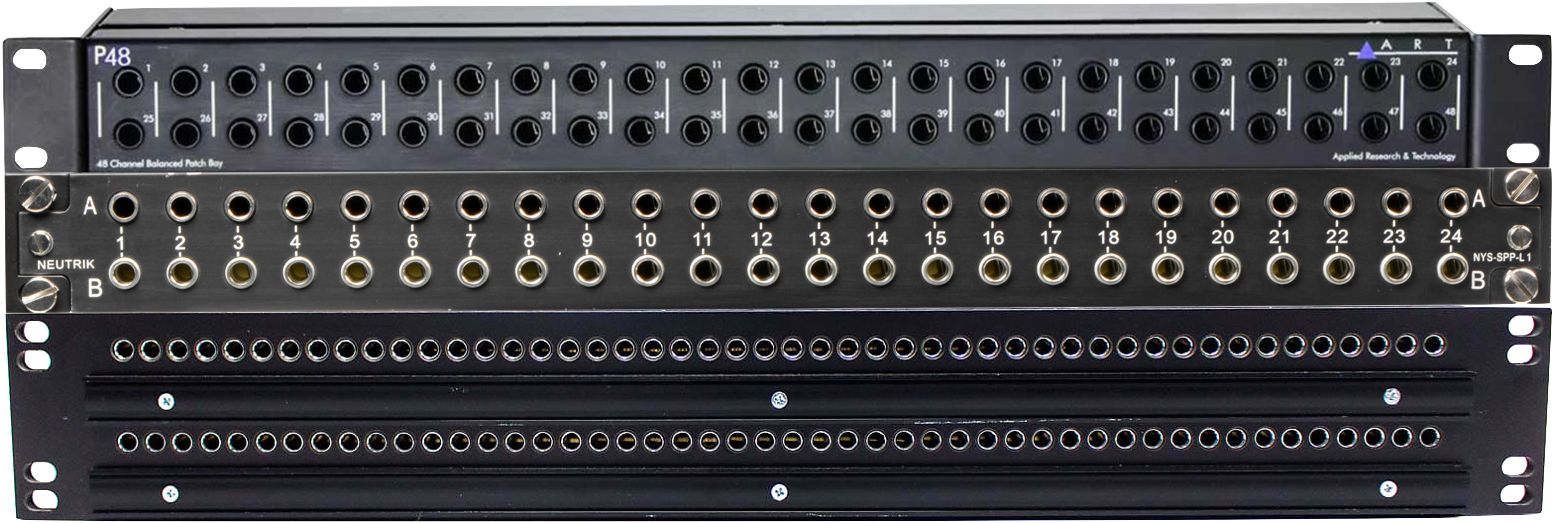
Studio Installation Workshop: Patchbays To do this, first cut the individual wires to the same length. Next, place one end of the wires in a vice, or hold with pliers. Finally, place the other ends in a drill chuck and then twist while keeping them taught. You will find that it is best to over-twist them slightly, as they will unravel a little when you release them from the chuck. Patchbays 101 — Layout, Signal Flow, Normalling & More Patchbay Design Typically, patchbays have 24 channels per unit. They handle both input and output for each channel, which makes 48 "points" or connections. Most modern patchbays use tiny telephone (TT), or bantam connectors on the front. Although, some patchbays use 1/4" TRS or even XLR connectors. Connecting an audio interface to a patchbay? - Gearspace.com Now draw a wide patchbay shaped box on a new diagram. One for each of your patchbays. Grid them off according to how many front ports. One row of 12 boxes for a Hosa XLR bay. Two rows of 24 boxes each for a standard quarter inch bay. Label the bays, but leave the port boxes empty. Make it pretty..this will be in use for a long time. PatchCAD 3 - Patchbay Design and Labelling Software Your patchbays are complicated and could do with making notes and instructions to help prevent mistakes and assist with wiring You do installation work and need a more versatile design tool that just labelling a patchbay or a panel Designing termination panels is part of your work PatchCAD 3 £25 Powerful editing tools
Patchbay diagram! - Gearspace.com patchbays Amen to the previous post. I'd keep your mic tie lines and monitoring paths out of the Patch bay. Use a half normalled mode to connect key pre's and out board to converters. The remaining gear can be routed via cables to the converter pb channels. Consider Placing on top racks spaces for ease of installation and maintenence. Recording Studio Wiring HELP! What a confusing mess ... Feb 25, 2022. #4. You are making it a little more complicated than it needs to be. First, the XLR wall box doesn't need to go to the patchbay, it can connect directly to the inputs of the console. You can just select the channel on the console by plugging in to the appropriate xlr on the wall plate. Downloads - Support - Whirlwind Ethernet Cable Wiring Diagram (21 KB - PDF) Whirlwind Transformer Color Codes (44 KB - PDF) Wire Color Codes (44 KB - PDF) Connectors. ... ADC Patchbay Labels (30 KB - XLS) Label Template for WLF482 and WTT961 (33 KB - XLS) Patchbay Label Template (470 KB - DWG) WTT961 Manual (22 KB - PDF) Patchbay Tutorial Please see the above instructions in action as a Quicktime movie on the "How to Wire a Patchbay" page. How to Setup Your Patchbay Videos Patchbay Movies. How to Make your Own Patchbay Lables These days another great method for making your patchbay labels is to get a Label Maker. You can pick up a good Label Maker for under $40.00 and there ...
Patchbay Wiring Diagram | autocardesign Patchbay Wiring Diagram sos forum What Cables for My Patchbay Setup Patchbay Wiring Diagram - wiring diagram is a simplified suitable pictorial representation of an electrical circuit. It shows the components of the circuit as simplified shapes, and the capacity and signal friends in the midst of the devices.
DIY Pedalboard Interface (FX Loop/In Front of Amp ... Below are the parts, templates, and diagrams you will need in order to build yourself a Custom Pedalboard Interface (AKA Junction Box or Patchbay) based around an amplifier with an FX Loop. XOXO, ~ Uncle Mason, The Rig Doctor PARTS LIST (Amazon Affiliate links included) 1) Hammond 1590BBK Enclosure Amazon ----
Need help wiring an ADC 24 channel TT patchbay - Cakewalk This is a crued diagram of the patchbay. oooooooooooooooooooooooo oooooooooooooooooooooooo oooooooooooooooooooooooo The bottom 2 rows both have 3 solder points on each input, and seem to be connected so that when you plug something into either of the jacks, it is disconnected from the other one.
How to Use a Patchbay | Sweetwater Create a patchbay diagram While there's no right or wrong arrangement for connections, be methodical with how you set it up and create a clear wiring diagram, also called a patchbay diagram. Some manufacturers will also include blank templates that you can use, as well. Creating a diagram you can refer to at any time will save you a lot of time.
Conveniently using stereo equipment in mono with a patch ... Apr 21, 2022. #7. The thing to remember is that all equipment, mono and stereo goes to the patchbay to either one channel, or two - so a 'stereo' device with 1 3.5mm stereo output goes to two channels on the patchbay, unbalanced. you can of course always take one source (on the top row) and over patch it from the top row to the next channel, if ...
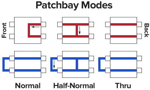
PB-48 Patchbay I NDERSTANDING PATCHBAYS AND THE dbx PB The front-panel lower jacks in a half-normalled/normalled patchbay are called inputs because each front-panel lower jack is wired directly to its corresponding rear-panel lower jack which is connected to an equipment input. Plugging into a front-panel lower jack interrupts the signal fed from
Patchbay Wiring Diagram: Route The Right Way | Multitrack HQ Product: Link A patchbay allows you to connect the inputs and outputs of your outboard gear into one place. You’ll be able to route a device to another without making any complicated changes. Plus, it doesn’t require you to use a whole lot of gear either. On the other hand, using a patchbay isn’t easy. That’s because it requires a bit of planning o...
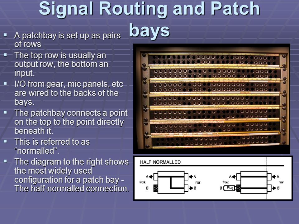
Half-normal patchbay configuration - Half normalling A half-normal patchbay configuration is commonly used with analog line level signals. The signal from the source device, at the top jack, flows through to the jack directly below, to a destination device, via the "half-normal" signal route. This type of normaling differs from a full-normal in that the signal switches o
Recording Studio Wiring, Patchbays, Audio System Design Specializing in custom analog audio patchbays. Mogami patchbays, Mogami custom patchbays, TRS longframe patchbays, tt patchbays, snakes for d-sub patchbays, legacy console wiring including SSL, Neve, MCI, Sony, DDA, Mackie, Soundcraft, and API. Custom analog audio snakes for all system designs, custom wiring for all analog audio systems.
Patchbay Wiring Diagram - schematron.org Nov 20, 2018 · A patchbay can make your studio much quicker to use, but can also be a If the machines were not wired via a patch panel this would be difficult, and would The normalled jack sockets will therefore look like the diagram in Figure 2a. At first, knowing how to use a patchbay seems like it would require a important due to the increased popularity ...
Patchbay + Multitrack BUILDING THE PATCHBAY SETUP This method involves connecting the direct outputs of the channel strips through the patchbay to the track inputs, and also providing the submaster bus outputs at the patchbay. First, determine if you have a Split console or an Inline console:
Patchbay Normaling How to Set the Normals for ADC Punch Down Patchbays. 48 Point Patchbays: To make Full Normal wire from Blue #1 to Blue #25. From Orange #1 to Orange #25; wire from Blue #2 to Blue #26 From Orange #2 to Orange #26 etc. To make Half Normal wire from Red #1 to Blue #25. From Black #1 to Orange #25; wire from Red #2 to Blue #26 From Black #2 to ...
Patchbay Setup Diagram BUILDING THE PATCHBAY SETUP. This method This is the SIMPLIFIED DIAGRAM used to represent either of the above types of mixers. It will be used in the. I'm thinking of getting a patch bay for my home studio. I'm still barely grasping the specifics of how to make this work. I've drawn up a diagram of. How to use patch bays in your recording studio.
PATCHBAYS R US - Dancetech I need some basic patchbay wiring diagrams. I am trying to "paper" design a project studio and I need to see schematic's from the mic panels all the way to the outboard gear. I still have no visual help to work with. I was hoping to have this with in the week. If there is anyway you might be able to help me in this search, e-mail me with the ...
The Basics of Patchbays: Patchbay Basics | Tape Op ... A patchbay is a central audio connection area for all the gear in a studio that allows any connection to or from equipment to be made in one location with a standardized cable and connector. Patchbays not only save time and headaches, they allow you to easily perform a number of mix tricks that would take serious head-scratching otherwise.










Comments
Post a Comment